
Coordinate a 9 m split solar light, pole and foundation supplied by different teams. Identify who issues and checks each interface before the assemblies reach the site.
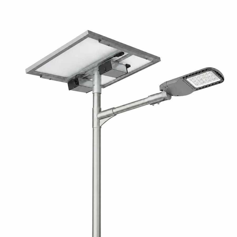
Mark which directions need light at each pole. Ask for the combined head load and align the anchor template and cable entry on the same drawing.
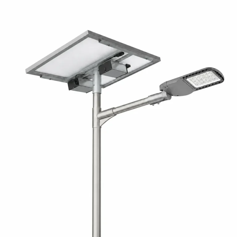
150 Wp separate panel · 1,408 Wh nominal battery in the series reference
Check that the battery box and independent panel bracket are shown on the same approved pole drawing as the 80 W head.
Send first
Send the road section, pole position, single or twin light directions, proposed panel location and the conduit side. For retained anchors, include the measured pattern and a photo of the base.
What to check
Ask for the approved arm orientation, circuit arrangement, base plate and template references on the same pole drawing. Use the combined lighting duty when two heads share power.
A 9 m central verge can need two heads, while an outside verge may need one. Start by drawing the lighting arrows and any asymmetry in arm reach. In the approved assembly, the base plate hole arrangement and cable opening then need to line up with the same pole orientation used in the optical design.
| Decision | What to send for review |
|---|---|
| One head or two | Road and verge section with head directions, arm projections and required lighting on each side. |
| Shared or independent power | Each head’s dimming profile and the required behaviour when either side is out of service. |
| Template and cable position | A coordinated base plate and anchor template drawing that shows the planned conduit and enclosure side. |
For a new foundation, review the actual templates and pole orientation before the pour with the civil and electrical teams. If the site already has anchors, record the pattern and condition and refer mismatches to the project engineer. The pole and foundation are checked for the final panel and arms under the applicable site conditions.

Two luminaires per pole · Separate solar panel
Compare this alternative when a central pole needs to cover both sides of the road. Confirm the output per head and the combined load before selecting the pole.
| Order item | Single arm | Double arm |
|---|---|---|
| Lamps | 1 head and 1 arm per pole. The SL-SPL-HC 80 W reference is an option. | 2 heads and 2 arms per pole. Approve the wattage and optic for each side. |
| Solar and wiring | Itemise panel, controller, enclosure, battery and wiring. | State the quantity of each component and identify shared or separate power sets. |
| Pole and site work | Check pole, base plate, anchors and template on the same drawing. | Check both arms and the panel area in the pole review. Confirm the base and anchor kit before the foundation pour. |
On a 9 m split installation, the lighting supplier, pole shop and civil contractor may each have their own scope. The parts that connect them still have to fit in the field. Write a short interface schedule starting with arm to head, panel to bracket, bracket to pole, enclosure to pole, wiring into the assemblies, and base plate to anchors and concrete. Name the party who issues the dimensions and the party who checks or accepts them. The buyer can attach that schedule to the orders so a missing connection detail has an identifiable owner.
Use the pole ID from the lighting layout throughout the documents. When the project crosses from a road into a work yard, the set of equipment on a pole can change. A few twin-arm locations or an extra camera can alter both the fittings and approval scope. Put the attached equipment and its position on one view for each representative group. Count poles, light heads and the supporting kits separately. The purchasing team can still order different packages from different firms while the site supervisor works from one location schedule.
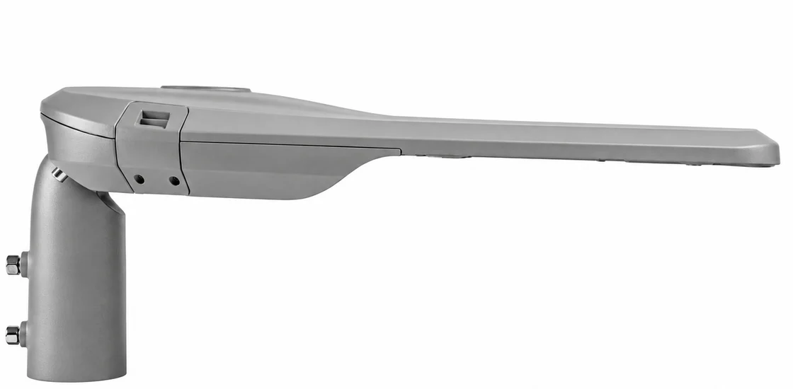
Request the exact luminaire drawing with the fitting, weight, intended orientation and service clearance. Ask for the photovoltaic panel outline, mounting positions and the assembly view identifying the bracket and enclosure. The pole shop needs to see where each part fixes and how the installer gets tools to it. A photograph of an open panel frame may help explain the layout but the shop needs dimensions and approved mounting details. If equipment can be arranged more than one way, call up the chosen bracket and enclosure position with the corresponding drawing.
Give the lighting team the real lamp height, arm reach and aim from the pole shop’s schedule. Ask the designer to evaluate the road or yard using the exact optic and operating mode. The drawing supplied to the civil contractor should carry the location and orientation the lighting designer used. Where a late change moves a pole or shifts the light over a kerb, ask the designer to check the actual effect before the installer repeats the new arrangement. Record which positions changed. A small layout change can be harmless for one area and important for a junction or narrow lane.
The pole shop should return a drawing showing the actual equipment layout and fittings, including any openings, internal routes and access. Ask the shop to identify the information it still needs to finish fabrication and the party responsible for confirming structural design. Supply the site conditions and equipment loads to that reviewer. A proposal can list a nominal height while still leaving steelwork, wind exposure, support details or foundation questions open. Keep the construction release and the calculations tied to the agreed assembly and site basis.
Use the equipment list to check which cables and attachments must pass or fit through openings as the pole is assembled. Show the sequence and the space available. If the local shop makes an enclosure recess or builds a bracket using the lighting supplier’s interface, confirm the mating dimensions before finishing the whole batch. Where suitable, compare one delivered part with the drawing at the workshop. Inspecting one pair of parts while both suppliers can still respond is often faster than discovering that neither can approve a change after the poles have reached the site.
Ask the pole and civil teams to use the same base plate, anchor, cable entry and locating template information. Identify the exact version and ground reference. The lighting assembly’s final position should be clear on the civil layout, including which side the arm and door face and where a cable duct arrives. If the ground level is changing after foundations are installed, use the finished surface in the height record. Check that the site supervisor can tie the foundation markings to the intended pole group before the work proceeds.
An item described as anchors may refer to rods, nuts and washers, with the template supplied separately. Give those components separate entries and identify whether the kit comes from the pole vendor or a civil supplier. Before casting foundations, the responsible parties should verify the approved geometry and how it will be set out. On an existing foundation, get the site report and field dimensions for the approved reuse review. Keep any requested changes to anchor layout or entry position together with the approved engineering documents and drawings.
Put the panel, controller, battery and luminaire connections on a drawing with circuit identification and the supplied and local cable sections marked. The electrician needs to know the cable type, measurements behind the selected route and where required protection and connection work fall in the installation plan. If the pole shop fits guides or prepares entries, include the relevant positions in its drawings. If the lighting supplier provides special connectors, agree how the installer identifies compatible parts and weather protection. Use the selected equipment instructions and the site professional responsible for electrical work.
Agree who sets the lighting profile and who checks the result. The installer may complete local connections while the equipment supplier provides a procedure and parameter record. The owner may ask a separate consultant to assess the lighting. Put those three tasks on the schedule with the records each party will return. If communications, backup power or site switches are a requirement, give them a separate interface entry so they are not overlooked in an apparent stand-alone kit. Verify the final design and equipment for these additions as their effects can extend beyond the electrical connection.
At delivery, photograph a discrepancy with the part identifier and the dimension reference that matters. Note whether the components came from the correct order and whether the supplier is using the current drawing revision. Send the issue to the assigned interface owner for review. If the foundation is ready, compare the field measurement to the approved template and base drawing before proposing changes. If a cable or cover needs more room, identify which enclosures and pole groups share that arrangement. A reviewed change can then be applied to its exact scope.
A practical way to make the handover easier is to add an interface column to each supplier’s delivery record. Give the pole vendor’s base drawing the same reference used on the civil template order. Give the luminaire and bracket the same reference used on the pole fabrication drawing. Ask the receiving team to take a photo of the labels or assembled sample for the critical connections. If the supplier proposes a substitute, record which connection it affects and the approval it needs. That record also helps the buyer check stock before a scheduled installation date without mistaking a box of similar fasteners for an approved kit.
At the first installed location, use the schedule to confirm that the bracket, connectors, pole and foundation information describe the working assembly. Include lighting checks and the operating programme in the signed record at the agreed conditions. Give the maintenance team the contact or document owner for replacement equipment, plus the part identifiers and compatible alternatives where supplied. If a future repair changes a bracket or equipment type, the same interface list helps the owner see whether anyone else needs to review the change. Build the file while the suppliers can still identify exactly what was delivered.
Specify head and optic for each direction. Put the counts for panels, batteries, controllers, cables and enclosure sets next to the number of single or twin poles.
Have civil and electrical reviewers check the arm, anchor pattern, cable entry and base orientation on the same revision. Resolve any existing anchor mismatch with the designer.
Before a repeat pour, compare the first template and conduit position with the approved drawing and the marked pole installation direction.
Before a foundation pour, place the pole base drawing, anchor template and conduit entry on one marked-up view. Confirm the hole pattern, bolt projection, washer clearance and cable access with the responsible parties. A label for the nominal bolt diameter will not tell the crew where the bolt lands or whether there is room to tighten it.
The project should identify a person or firm responsible for the pole design and approval. Give that party the actual lighting, solar and enclosure details and the site conditions. Have the equipment suppliers confirm their interfaces, then use the approved drawing at the site.
Confirm the approved template geometry and who warrants its match with the base plate and approved anchor set. Show the cable-entry and orientation requirements on the same drawing set. The civil team can then check and record the installed setout using the project’s approval process.
Freeze the route geometry, the interfaces that govern civil construction and the equipment loads that will be used in the approval. Identify proposed parts and open constraints. Record which party can sign off each remaining decision and the latest point at which each drawing must be approved.
Update the pole and equipment schedule by location. Confirm the weight and position of both heads, panel and enclosure arrangements, and relevant loads with the responsible reviewer. Recheck light and energy design where the operating tasks differ. Count the hardware and spares from the final schedule.
Share a plan and the instructions you already have. State who supplies the head, panel, pole and civil work, and identify any foundations that are already in place. Ask for the missing dimensions or records that could change those decisions before you issue production orders.
Ask each vendor to identify cartons by the common assembly or position reference whenever practical. Keep a master receiving list with the packages and quantities from each order. If a bracket or anchor kit is missing, the site team can see which order it belongs to and which locations can still proceed. Track uninstalled items in the same schedule until someone confirms receipt and fit.
Keep both source values and send the discrepancy to the responsible designer, including the drawing revisions. Continue the affected fabrication or foundation work after one revised detail is approved.
Specify who supplies the template and when it must reach the civil crew. Record it as a line item in the delivery plan, even when another party supplies the anchors or the pole.
Check the final pole base drawing, its reviewed structural loading and the conduit and arm orientations. Get the coordinated drawing approved before using a template from a different configuration.
Send the site layout and who supplies the light, panel, pole and civil works. Include the drawings or field dimensions you have.
WhatsApp us