
Compare panel and bracket options for a 10 m split solar light. Check the roadway coverage, the equipment the pole must carry and how the owner will service it.
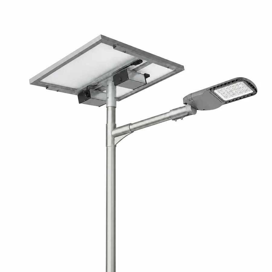
Send the final panel dimensions and its offset from the pole. Use the same revision for bracket loads, the pole drawing and the component list.
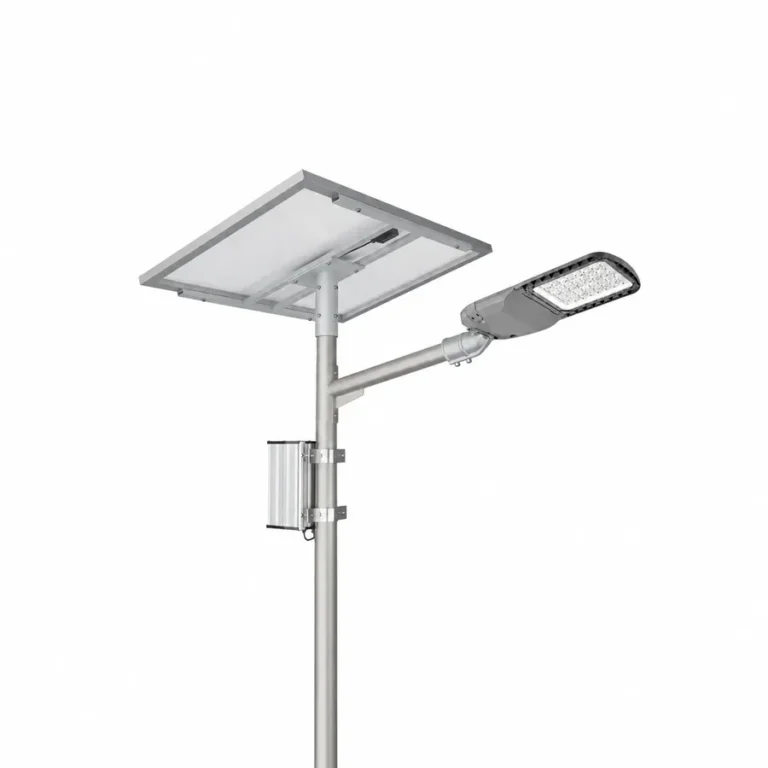
200 Wp separate panel · 1,664 Wh nominal battery in the series reference
Compare the 100 W model with the proposed panel tilt, wind area and bracket details on the selected pole.
Send first
Send the current and substitute panel drawings, fixing points, voltage range, mass, dimensions and offset from the pole. Reference the original equipment and foundation drawing numbers.
What to check
Ask electrical and structural reviewers to check the same proposed assembly. Obtain the approved drawing revision before changing the BOQ or releasing affected foundations.
A panel swap at the same nameplate wattage can still change dimensions, mass and clearance. For the 100 W SL-SPL-HC reference, compare the supplied parts list and panel drawing with the proposed substitution before the design is approved. Show the mounting height, offset and cable exit on the revised assembly.
| Before approving the change | Check who owns it |
|---|---|
| Electrical match | Confirm working voltage, controller input limits and connection details for the actual replacement panel. |
| Bracket and pole match | Review hole positions, panel mass and exposed area with the structural reviewer using actual site design inputs. |
| Purchase and receipt | Record the drawing and BOQ revisions, then check the delivered panel label and bracket against them. |
Keep the original line beside the replacement so the project team can see why it was offered, what is changing and what evidence is needed. A wider panel may change the pole review even if its wattage matches the original. Leave the foundation release with the design authority until the final assembly is agreed.
| Order item | Confirm in your BOQ |
|---|---|
| Lamps | List the selected head, optic, arm and orientation for each lighting direction. |
| Solar | List the panel model, dimensions, fixing points and tilt. Match it to the controller, battery, enclosure and cable schedule. |
| Pole & base | Price the pole, base plate, anchors and template as separate BOQ lines. Confirm the equipment loads and wind inputs before approval. |
Start with where staff or vehicles need light and which gaps on the road or work yard matter. On a 10 m layout, mark edges, turning areas and long spaces between poles on the same plan as the proposed mounting heights. Give the calculation team the site dimensions and the exact fitting, aiming and operating condition to model. Review the lowest values in the critical areas and any criteria set by the owner. A panel choice should follow the electrical load and the available charging, while the optics and site layout determine where the light reaches.
An independent solar panel gives the design team more freedom to position and angle it. It also adds its own bracket and exposed surface to the installation. Compare the positions that are practical for charging, access and cable routing. A site with far-apart poles may need each light to carry its own separate solar system. At a yard with obstructions, moving a panel away from one position might be practical if there is a suitable place to fix it and run the correct circuit. Identify those differences before making one assumption for the whole site.
Our files include a previous 10 m pole calculation that began with the number and size of the proposed photovoltaic modules. Use that approach when a panel changes. Give the project’s structural reviewer the selected panel dimensions and orientation, the supporting bracket and its position, the luminaire arm and all other attachments. Include the lamp and enclosure weights, the mounting details and the site information required by the responsible reviewer. Keep the assumed equipment geometry visible on the assembly drawing so it can be compared with what will be bought and installed.
A change from one module assembly to another can change projected area, attachment loads and how forces are passed into the pole and foundations. Have the responsible reviewer assess the site design basis and full installed arrangement. Read the scope of any supplied structural report before using it for a different job. A historical calculation may help define what drawings and inputs to ask for. The approval for this site must follow the equipment and conditions on this project. Make sure any foundations that already exist are included in the review when they will be reused.
Give the pole shop the equipment’s mounting interfaces, enclosure access and necessary routing information. Then ask, on the returned pole assembly drawing, where the bracket and arm sit and where the cables enter. Check how the base plate and anchors are identified on the civil and fabrication drawings. A previous drawing review in our files found two different anchor descriptions on the same sheet. If a callout and an enlarged detail disagree, request an issued revision so the supplier and civil team use the same confirmed part instead of reading two instructions from one drawing.
At the interface with foundations, record which revision controls anchor dimensions, template and orientation and which party checks it before installation. Existing foundations may require a field survey and engineering review. For new construction, share the released information with the site team before templates are set out. If the civil contractor and pole supplier source their parts separately, have them check that the actual base plate and anchor kit match at an appropriate stage. Keep the approval and any revised installation drawings together so one change can be followed through the supply chain.
Set the estimated equipment load by working mode and give the supplier the required hours and reserves. Ask for the expected charging basis using the installed panel direction, slope and relevant constraints. A wider panel may improve energy recovery if it can be sited with a useful solar window and the controller and battery can work within the configuration’s limits. Where a panel is partly blocked, compare a different position before paying for additional panel area. The comparison needs the actual obstructions and the intended cable route rather than a generic description of outdoor conditions.
Prepare a layout showing the head, controller, battery and panel positions and how the wiring connects them. Confirm which cables and protections come with the kit and where site work begins. At positions that differ, document whether an enclosure is under the panel or at another location that the installation and maintenance teams can reach. Changing the panel or enclosure position can change both the electrical design and the physical arrangement you had assessed. Ask for the relevant drawings and approvals together as you review the option for fabrication or site installation.
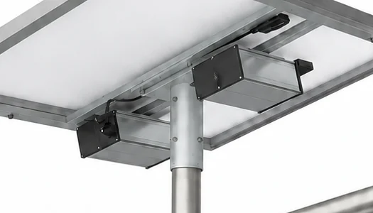
At a several-row work yard, the panel may be easy to install before fencing or production begins and harder to reach later. Have the maintenance team show how a vehicle or platform will approach each pole group. Identify the working space around the bracket and enclosure and any power lines, buildings or equipment that constrain access. Choose the cover and connection orientation as part of the proposed design. Where routine service can be brought lower on the pole, review weather and access conditions along with the altered wiring and structural arrangement.
Check whether the panel, enclosure and light can be serviced separately and which fasteners and connectors the crew needs. Ask the supplier to identify the parts and provide the relevant access and isolation instructions for qualified personnel. Note which spares are specific to this layout, particularly where part of a site carries a different battery or controller. A fixed maintenance cost can become significant when a bracket needs access from a constrained side of every pole. Include both the first installation and likely maintenance work when comparing a shorter or extended arrangement.
Pick a representative installation that tests the panel bracket, luminaire aim, electrical routing and whatever access condition drove the design. Have the installer match the physical parts to the approved material list and records. Inspect the layout view against the positions actually built and verify the selected programme. Agree lighting measurement points in the critical areas; record the operating mode and which other sources are present. Check the solar aspects using the selected commissioning procedure and relevant daylight conditions. A trial can reveal whether the mounting and service arrangements work as the drawing assumed.
Check whether a larger module affects packaging and delivery at the same time as the bracket. A panel that fits the proposed structure may still be awkward to handle where the road is narrow or enter through a restricted gate. Give the contractor the packed and unpacked dimensions and agree where the equipment can be received and secured before installation. If the site is receiving separate shipments, mark which panel frame and fastener kits belong to each pole group. Check whether the local delivery route changes the order in which the panel, pole and bracket reach the site. When installations are phased, keep the receiving list tied to the proposed sequence so that the crew knows which fittings should be on hand before traffic arrangements or access equipment are booked.
Keep the signed record and drawings under the same references as the delivered equipment. If a proposed fix changes a loaded bracket, a cable circuit or the aiming design, identify the affected approvals and resubmit the appropriate details. Apply the released change only to the positions that use it. Prepare an installed asset list with the panel, controller, battery and lamp references, and add the applicable assembly and civil drawings. The next crew can then compare field parts to the installed version after the project manager or original supplier has moved to another job.
Record the original and proposed panel codes plus controller limits, working voltage, connector and lead details.
Record changes in projection, exposed area, mass and hole locations. Confirm which parts of the pole or foundation review need updating and who signs the change.
Put the approved substitute on the BOQ and packing list. Review the first panel and bracket labels against the drawing before accepting a delivery.
In Project details, identify both panel references and the drawing revision. If your drawings are restricted, ask how to send them.
A larger panel can improve energy collection while changing the bracket, wind area and electrical limits. Put the proposed panel part number, dimensions, weight, orientation and electrical values into the same revision as the pole equipment drawing. Then ask the responsible parties to review both the electrical fit and the structure before changing the order.
Review the light distribution and layout first. Changing the solar panel can support the required load if it improves the energy balance. A dark spot can still result from beam shape, spacing or aim. Ask the reviewer to identify what change is expected to improve each result and check the revised equipment as a system.
Give the external dimensions, attachments and positions of each proposed panel and bracket to the responsible structural reviewer. Ask for the approval scope for the pole, connections, anchors and foundations. The accepted combinations should be identifiable in the equipment schedule and the drawings the installer receives.
Discuss how the crew will reach and work on each component before fixing the layout. Check whether moving the working side or locating serviceable equipment elsewhere is possible, with wiring and structural details reviewed. If the site can only be accessed during limited times, plan the longer service task into the ownership comparison.
Have the lighting reviewer and owner agree which points, areas, modes and criteria apply. Include edges and spaces between poles where visibility matters to the job. Record conditions and nearby light sources. Plan the daytime charging and controller checks separately so both aspects of the same installed system can be assessed.
If the model, optics and output remain the same, ask the lighting designer to confirm how the same file applies to the revised geometry. Recalculate the actual aim and pole position where they changed. Check that the new equipment arrangement was also shared with the structural and electrical reviewers before site release.
Check the dimensions, frame fixing locations, mass, voltage and current before approval. Equal nameplate power alone does not establish compatibility with the mounting hardware or controller.
Compare the panel label and bracket part against the approved list. Check that the fasteners, cable and instructions match that revision, then assign the equipment to the intended pole group.
Use the currently approved drawing for release decisions. Route any late substitution through the electrical and structural reviewers and obtain an approved revision before committing the affected work.
Send the proposed panel and bracket dimensions, road layout, available access positions and pole or foundation drawings.
WhatsApp us