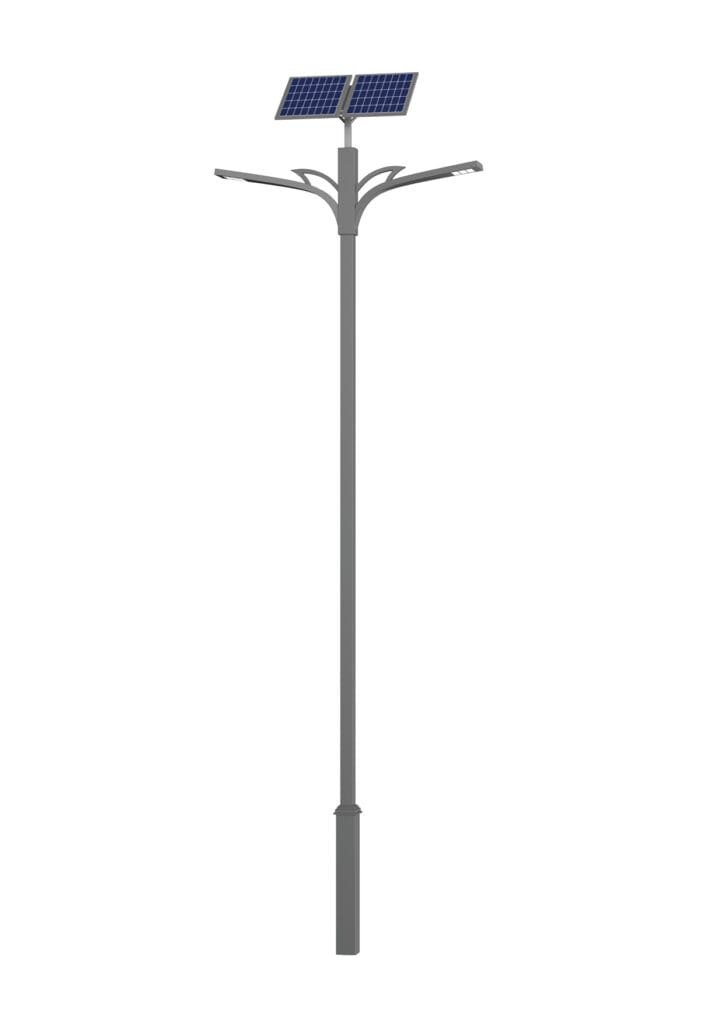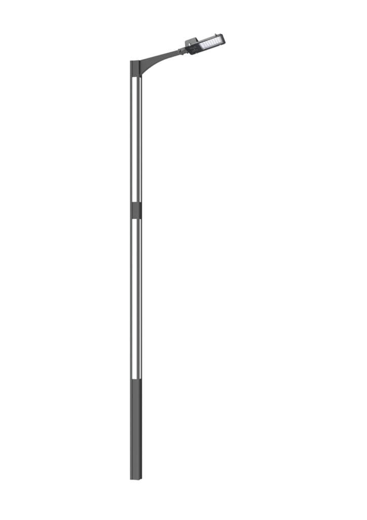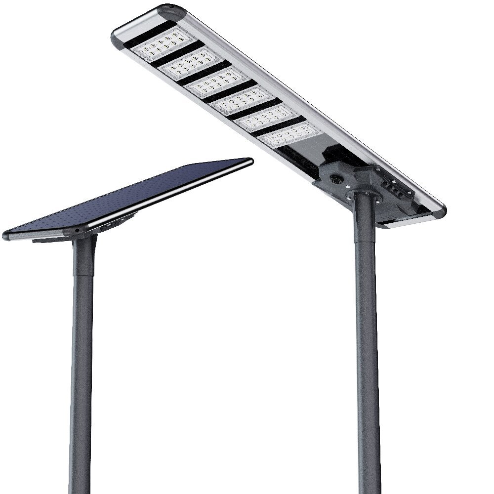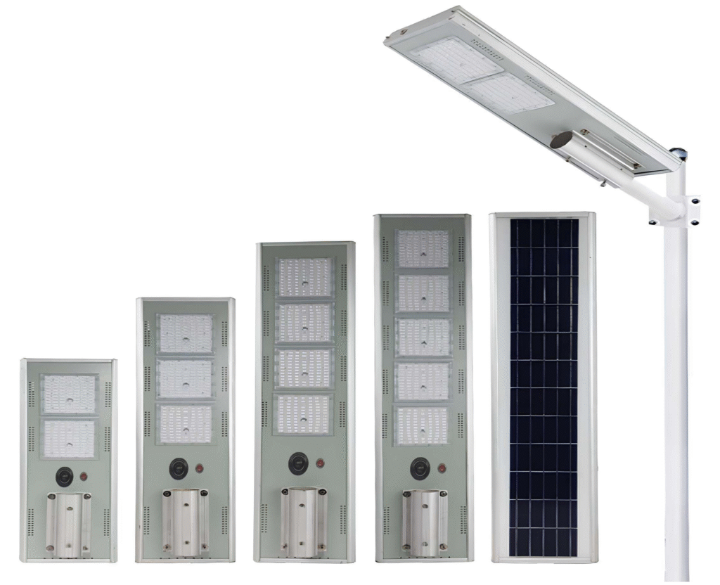
A road-lighting solution should connect the road cross-section, pole arrangement, mounting height, spacing, optical distribution, lighting target, power system, structure and tender requirements before an exact product configuration is selected.
Sunlurio supports EPC, municipal, consultant and infrastructure teams with project review, DIALux/Relux coordination, model-matched photometric files, drawings and BOQ clarification.
No fixed spacing, wattage or road-class result is promised without geometry and photometric review.
The same nominal wattage can produce very different results when the road width, pole arrangement, height, spacing, arm, tilt or optic changes. A defensible solution follows this sequence:
Road geometry → lighting target → pole arrangement → product/power path → model and optic → simulation → structure and documents → acceptance
Starting with a wattage or fixed spacing creates predictable risks: dark zones or weak uniformity; excessive glare or light outside the target area; unnecessary poles or an under-designed layout; mismatched solar energy/autonomy; structural or foundation conflict; BOQ, model, drawing and photometric-file inconsistency; and disagreement between the design report and as-built acceptance.
Decision note: Pole height and wattage are inputs—not a complete road-lighting design rule.
Country, city or coordinates; highway, arterial, collector, rural, municipal or other defined road context.
Road width, carriageways, lane count, median, shoulders, sidewalk or cycleway, setbacks and nearby constraints.
Existing or proposed pole positions; single-side, staggered, opposite or median arrangement; pole height; spacing; arm length or overhang; tilt and orientation where available.
Road class or tender/consultant target where specified; maintained illuminance or luminance basis; uniformity, glare and local acceptance criteria.
Solar, grid AC or existing infrastructure; voltage/frequency; operating hours; dimming; monitoring/control; autonomy where solar is considered.
Wind, corrosion, dust, rain or flooding, pole/arm condition, anchors, foundation and soil/site information.
CAD or road plan, cross-section, survey, pole schedule, BOQ, tender specification, required documents, project stage and acceptance or handover requirements.
If inputs are incomplete, a preliminary review can identify assumptions and missing information. Formal simulation and configuration require the inputs that materially affect the result.
Single-Side: may be reviewed where geometry, setback and the selected optic can serve the target area from one side.
Staggered: may help distribute poles between sides, but spacing, transitions, uniformity, access and maintenance must be coordinated.
Opposite: may provide a symmetric starting layout while increasing pole quantity and civil/electrical scope.
Median / Twin-Central: may be considered when median, arm arrangement, access, traffic safety and structure support it.
Road width alone does not decide the layout.
Solar, grid AC and hybrid or phased road-lighting paths solve different infrastructure and operating conditions. Product selection follows the confirmed project path—not a wattage-only rule.
Review local solar resource and shading, operating hours and dimming, autonomy or low-solar period, PV/battery/controller architecture, component position, pole loading, maintenance and tender documents. Year-round operation depends on confirmed solar resources, load, dimming and autonomy; it is not an unconditional no-blackout guarantee.
Review voltage/frequency, existing cabling and cabinets, pole/arm interfaces, driver, surge protection, earthing, optic, dimming, control compatibility and retained infrastructure.
Consider only when the grid, solar, existing assets and operating responsibilities justify it. It is not a universal cost-saving label.
Connect the road cross-section, pole position, setback, mounting height, spacing, arm/tilt and target metric to the selected luminaire and photometric file. Type II and Type III are available as family capability; additional distributions, including Type IV where relevant, require model and optic verification. A generic IES/LDT file must not be used across different optics, models or BOMs.
Request Model-Matched IES / LDT
Sunlurio can review standard road-lighting configurations from approximately 3 m to 14 m mounting height. This is a capability range, not a rule assigning wattage, spacing or road class. No fixed spacing or road-class promise is made without geometry and matched photometric review.

A project-level simulation combines road geometry and calculation areas; pole positions, arrangement and spacing; height, arm, tilt and orientation; lighting target and maintained-value basis; exact luminaire, optic and photometric-file revision; and maintenance-factor assumptions.
Outputs may include layout, maintained illuminance or luminance where applicable, uniformity, glare-related metrics, calculation grids, luminaire/optic identification and comparison of reviewed alternatives. Every result remains tied to its inputs, assumptions and report revision; a sample or older simulation does not guarantee another road or configuration.
Where possible, confirm the governing maintained illuminance or luminance basis, uniformity, glare and local acceptance criteria. Average light level can conceal dark zones; more output or greater tilt is not automatically better. No universal lux, uniformity or glare value is assigned without the road target and geometry.
Review pole material and section, height, arm and luminaire arrangement, solar-module loads where applicable, wind and corrosion basis, flange and anchors, foundation or soil information, cable and earthing interfaces, cabinets, maintenance and installation access. Pole thickness, flange, anchors and foundation dimensions must come from approved drawings and project inputs; a generic foundation reference is not a final structural design.
Confirm the operating schedule, driver/controller compatibility, communication and network availability, platform/interface/data requirements, cabinet or gateway scope, commissioning and O&M ownership. Scheduled dimming, 0–10V, DALI or wider smart functions are conditional; no protocol or platform feature is universal.
Public files are limited to current approved buyer checklists or documents. Matched datasheets, actual IES/LDT, project DIALux/Relux, structural or wiring drawings, BOQ compliance/deviation and full certificate/test or tender packs remain controlled after the model/BOM, geometry, project stage and release scope are confirmed.
Drawings & Datasheets · Tender Documents & BOQ
Acceptance should align the specified target, approved model/BOM and optic, matched photometric file and report revision, approved pole geometry, installed/as-built configuration, agreed measurement conditions, recorded deviations and handover documents. DIALux/Relux support does not promise government or consultant approval; acceptance follows governing documents and verified as-built conditions.
Historical configurations are evidence for the named project—not universal design rules. Solar and AC records remain separate.
Togo Road & Highway Solar Street Lighting
2018; 13,000 All-in-Two solar street-light sets; 60W LED; 8 m hot-dip galvanized steel poles; Accepted. Support included IES/DIALux and tender technical coordination.
Ghana Main Road Solar Street Lighting
2015–2020; 12,000 All-in-One solar street-light sets; 80W LED; 9 m poles; Completed. Support included IES, BOQ, DIALux and tender coordination.
USA Rural Road AC LED Street Lighting
2024; 210 AC LED street-light sets; 60W LED; 7 m poles; Completed. Support included IES, DIALux, pole drawings and wiring diagrams.
India Main Road AC LED Lighting
2016; 420 AC LED street-light sets; 60W LED; 7 m octagonal steel poles; Completed and Accepted. Support included complete-system technical documents and on-site installation guidance; installation remained the client/EPC scope.
Evidence boundary: Client names remain private. Each quantity, wattage, height, status and file scope belongs only to the named historical project.

Share constraints and receive a solution-ready response.

Typical constraints by region—coastal, hot, dusty, and heavy-rain environments.
No. Spacing also depends on road geometry, pole arrangement, optic, setback, arm or tilt, lighting target, uniformity, glare and civil constraints. Review the actual layout with the matched photometric file.
Provide the road cross-section, pole arrangement, height, spacing, arm and orientation where available, lighting target, maintenance-factor basis and proposed luminaire or optic. Missing inputs must be stated as assumptions.
No. It records a calculation for stated inputs and a specific photometric file. Approval also depends on governing requirements, approved configuration and as-built conditions.
Review grid availability and reliability, solar resource, runtime, autonomy, existing infrastructure, maintenance, voltage and electrical scope, environment and procurement requirements.
There is no universal optic. Type II and Type III are family paths; additional distributions require model and optic verification against geometry and targets.
An average value can conceal dark zones. Uniformity shows how consistently light is distributed across the defined calculation area.
Only if geometry, luminaire, optic, BOM, file revision, target and assumptions are proven applicable. Otherwise request a new matched review.
Output and distribution, height, tilt and orientation, pole position, road geometry and observer context all matter. More tilt or power is not automatically better.
The list may include BOQ review, matched datasheets, IES/LDT, DIALux/Relux output, structural or wiring drawings, deviations, compliance evidence, packing information and warranty terms. The exact list follows the tender and confirmed configuration.
WhatsApp us
Share your project location, road width, pole height, spacing, working hours, backup days, and required documents. Our team can help prepare configuration guidance, datasheets, IES/LDT files, DIALux support when applicable, drawings, and BOQ matching notes.