
Plan how the site team will install and service an 11 m split solar light. Review the attached equipment, working clearance, enclosure position and cable paths together.
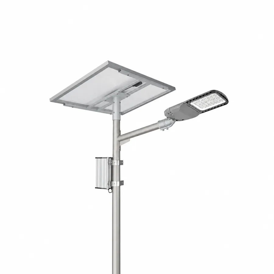
Confirm how the access door opens and measure the removal path. Include part references and connector types in the spare-parts list so the crew can order the right item.
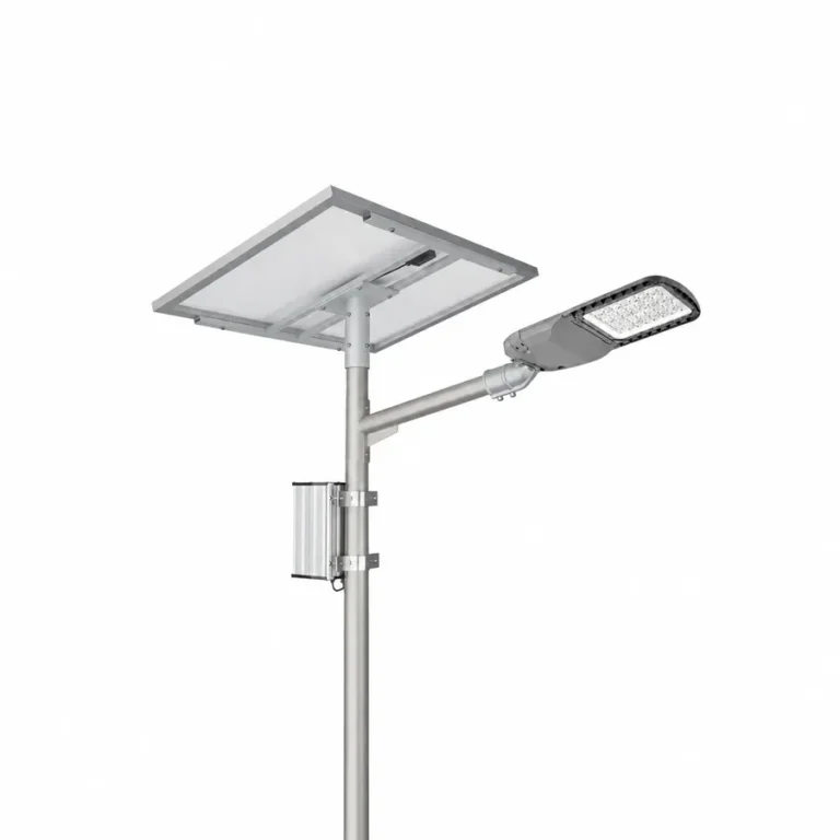
200 Wp separate panel · 1,664 Wh nominal battery in the series reference
Check which side the enclosure opens and where the lift can stand before you freeze the battery and panel positions.
Send first
Send the enclosure position, which way the door can open and who receives and services each batch. State the sample, packing or training requirements in the project RFQ if there are any.
What to check
Ask for the supplied enclosure layout, battery and controller part references, connector details and the route for taking a part out. Check the dimensional fit with the access available locally.
Use the proposed 100 W split layout to review the cabinet with the people who will maintain it. Draw the direction the door opens and the path a battery or controller takes on removal. A drawing should make clear whether the part can be removed while the rest of the enclosure stays installed.
| Spare or interface | What to capture before the order |
|---|---|
| Battery assembly | Part reference, nominal voltage, compatible controller or BMS requirements, connector and physical dimensions. |
| Controller | Hardware version, terminal arrangement and a record of the installed profiles. |
| Door, glands and cables | Door swing, fastening and seal detail, and the cable entry layout used on the installed cabinet. |
Build the initial spares list from the approved assembly. Label cartons with the subsystem and pole family in the equipment schedule. Agree who keeps the settings record and whether the crew can perform each replacement with the access and tools available on site.
| Order item | Confirm in your BOQ |
|---|---|
| Lamps | Record the head model, optic, arm and mounting parts for each pole group. |
| Solar | List the panel, controller and battery part numbers, box opening direction and supplied connection leads. |
| Spares | List the spare controller, connectors and battery by exact part code. Confirm the pole, bracket and anchor kit against the approved drawings. |
At 11 m, the location of each component affects how the crew will install and later service the system. Mark the light centre and arm, the solar panel and its bracket, the controller, battery enclosure and cable path separately. Put their weights and supplied connection points on the project equipment drawing, alongside any equipment already on the pole. The design team can then assess the actual assembly together with the conditions at the site. The installation team can also see which components need access together and which parts they can handle separately.
Find out how the local contractor normally reaches this height and where the access equipment can stand. Identify route restrictions, traffic, overhead services and the distance from the pole. A position inside a fenced facility may present very different access from a road verge. Put the information in the site package for the responsible contractors. Ask them what assembly and service options are practical under their approved procedures. It is easier to move a cover or choose a better bracket before the pole and electrical equipment have been released.
Ask the supplier to show the selected panel’s outline and mounting hardware, including its angle and position relative to the lamp and the shaft. Review where workers need room to position the parts, perform the specified fixings and route leads. A panel corner or bracket can create a working restriction even when the final assembly looks clear on an elevation. If there is more than one supported bracket option, compare their access and solar positions before the drawings are signed. Show common and exceptional locations separately so a different fixing does not get missed.
The same envelope belongs in the structural review. Give the reviewer the equipment geometry, weight and positions, relevant site information and any spare capacity assumptions the project wants to assess. If the pole will also hold a camera or signs, include the devices and their proposed locations. A reference drawing from an 11 m pole used for another type of lighting can show how to organise such information. Use the approved issue for the proposed split assembly and after any significant equipment change. Check which information applies to each type of pole and foundation.
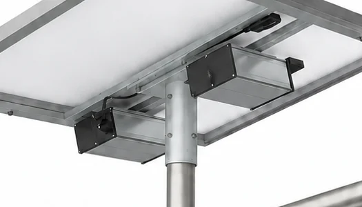
Check whether routine access to a particular enclosure requires the same equipment as access to the light and panel. Discuss whether the battery and controller can be reached individually. Show the cover opening and equipment removal path, plus enough dimensions to compare clearance at the mounting point. If a lower box is proposed, note whether workers can reach it without crossing traffic and consider the impact of water, access control and the local environment. Ask the equipment supplier to evaluate cable and electrical changes for that arrangement using its actual circuit requirements.
Decide how the parts can be moved on and off the equipment position under the contractor’s approved method. Component weights and mounting information help the contractor choose a suitable approach. Keep lifting and work-at-height planning with the qualified site team, informed by the actual product documents and conditions. Give them the equipment identifiers and which hardware is supplied. Where different poles have enclosures in different places, label the alternatives on the drawing and in the service list. That gives the team a clear check before it prepares an installation or an access visit.
Draw the actual cable path past brackets, below the panel and into the pole or enclosure. Distinguish the panel, battery and luminaire circuits and show where each will be connected. Ask the supplier to provide circuit and connector details and the named local items the contractor will fit. Give the installer the positions and access needed to handle the cables in the agreed installation method. If an entry at the head will be covered by a bracket later, show when it has to be reached and coordinate that step in the approved site sequence.
Service follows a different order from new assembly because adjacent components remain in place. Ask which circuits are accessed to replace a selected part, which instructions apply and whether the enclosure opens fully at the installed angle. Record any access and cable identifiers in the maintenance handover. A labelled drawing can save a return trip when the crew arrives with a replacement component and finds that the other connections are still live or that a lead is too short. Have the system supplier confirm component and configuration references at delivery.
Ask the lighting designer to use the installed light centre, setback and arm geometry for the proposed row of poles. If the lamp moves to allow access, check the effect on the roadway or working area before the change is released. Model the mode that the owner will use at the relevant time. Put the panel location into the separate charging review and give the supplier the site exposure, temperature basis and required service schedule. Describe the service conditions during the period with the weakest charging that the owner expects the installation to cover.
If the charging review suggests a change to the panel position or size, compare its effect on the installation order and structural assumptions. A provisional configuration can show where more information is needed. Before a final order, record which component layout and document revision the approved performance assessment used. This gives the civil and lighting teams a common view of what will be built. It also helps a subsequent reviewer confirm which calculations should be checked after a change in attachment height, panel dimensions, cable route or weight.
Use the first approved position to confirm that the configuration, planned access and installed parts all match. Have the contractor review who brings the brackets, cabling and external equipment and how components will be identified on arrival. Confirm that the planned access and working side are available. Take photographs of the installed pole from angles that show the principal connections and enclosure position. Have the project team check the operating profile and the lighting under the agreed conditions. Confirm that the data recorded for the test apply to the final equipment.
Ask the maintenance lead to describe the first replacement they are likely to face, such as a controller or a damaged cover, and follow that scenario through the installed arrangement. Confirm how the worker reaches the relevant location, finds the correct connector or fixing and identifies the matching replacement. The supplier can then address missing instructions and the owner can check whether local spares are practical. Have the field team check that the planned storage position is available for the removed part. Include a record of the position, access and parts in the commissioning file. A maintenance rehearsal can be done on an approved sample before every pole has the same avoidable obstruction.
Before repeating the work, identify any changed part or installation assumption and get the relevant review. At handover, give the owner the installed configuration by pole group, along with electrical information, access references and accepted spares. Keep the supplier’s service information together with the equipment identifiers and control settings. Where later maintenance could affect lighting temporarily, record which areas and modes the installation is expected to serve. A useful handover lets the next team plan its work and then check that the road service has been restored.
Keep the installed controller version, connector type, battery code and dimensions, door seals and glands alongside the proposed spares. Identify any parts a local partner supplies.
Ask what is included for packing, handover, training and replacement stock, and where the equipment is handed over. For an agency RFQ, use its named delivery point and forms.
Hand over the cabinet photos, labelled wiring and installed settings. Confirm who can identify the hardware from a fault photo and arrange the agreed spare.
Use Project details for the receiving team, service locations and the spare parts you need. Include a shareable cabinet drawing if you have one.
Put each enclosure and controller revision on a service sheet with the pole identifier, battery voltage and connector part numbers. Carry out one access check with the same side and space the service lift will have after opening the road. A spare cabinet or battery only helps if it matches the installed equipment and the crew can safely reach it.
Ask which configurations the supplier and designer support, then compare installation and replacement access for the assembly. Keep the exact geometry, attachment data and weights together. Ask the responsible structural reviewer to consider the loaded arrangement before choosing it.
Compare where the crew can work, whether the enclosure can be protected and the changes to wiring and its support. If access is improved for the most common service work, request the proposed adjustments in the equipment and pole drawings. Confirm that the final placement still suits the electrical and environmental needs.
Ask both contractors to explain the working space they need at typical and awkward positions. Mark any parts of the site that become unavailable after construction. Give the reviewers the equipment positions and maintenance tasks they will need to assess. The proposed service arrangement should be accessible under the owner’s normal conditions.
Show the emitting centre, panel, supports, enclosure, pole interface and other loads with their positions. Use a coordinated cable and civil reference set. Include the relevant access geometry and which component drawings describe the interfaces. That gives each party the same basis to review the installation.
Compare the equipment layout, cable path, access and service position with the groups it is meant to cover. Mark the positions with materially different arrangements and review them separately. The same sample can support common items while a specific bracket, enclosure position or access limitation still needs its own evidence.
Have the installer and maintenance lead check the list against the actual labelled equipment. Identify which items can be changed at the blanket service level and which need a scheduled access visit, a compatible connector or a settings backup. Store the component references next to the pole records, so a future repair starts with the installed arrangement and the correct supplier document.
Confirm that battery voltage, wiring, input limits and the lighting schedule match. Keep the approved controller reference and settings for each pole group even if some groups share a spare.
Record the pole number, model, time, weather, operating mode and fault display before doing more resets. Follow the applicable service instructions and leave electrical checks to qualified personnel.
Match the part reference, connector, physical envelope and controller or BMS requirements. Confirm compatibility with the actual installed revision before buying stock for the route.
Send the equipment layout, working-side constraints and access equipment available, along with the pole details and lighting schedule.
WhatsApp us