
Coordinate the approved equipment and drawings for a 12 m split solar street lighting project. Keep the optical design, separate panel, pole and civil interfaces on the same revision.
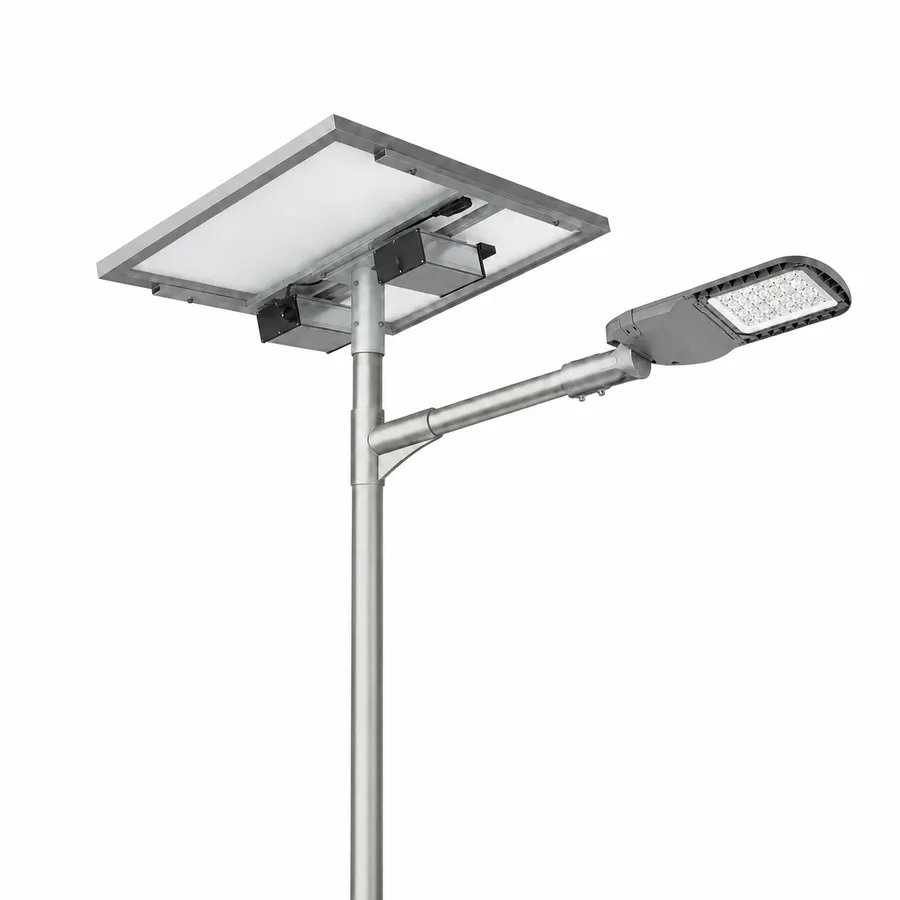
Send the number of heads, panel position, enclosure location and site wind design input. Use the same equipment drawing for the pole, foundation and anchor schedule.
250 Wp separate panel · 2,048 Wh nominal battery in the series reference
Review the 120 W head per lighting direction. Confirm the equipment positions, pole and foundation interfaces before ordering.
Send first
Send the latest BOQ and road plan, head count and direction at each pole, equipment layout, site design criteria, receiving point and tender clause numbers if applicable. Identify who designs the foundations and who accepts the installation.
What to check
Ask for the actual fixture and optic, cable and power schedule, and pole and anchor drawings tied to one equipment revision. For an agency or donor-funded RFQ, share its required forms and deadlines so each deliverable can be assigned.
For the 120 W split reference, agree the actual head count and each direction before the structural reviewer receives the drawing. Add the panel dimensions and mounting offset, enclosure placement, and the site design inputs. Keep this same version in the equipment BOQ and the drawings issued to the foundation team.
| Approval owner | What must match the final equipment |
|---|---|
| Lighting designer | Head and optic by position, actual installed height, aiming criteria and the agreed site check. |
| Electrical lead | PV and controller combination, cabinet arrangement, cable routes and documented commissioning settings. |
| Structural and civil reviewers | Final equipment weights and areas, arm offsets, their site design criteria, and the matching base plate, anchor and foundation drawings. |
When a part changes, identify its effect in all three submissions before reissuing the package. At receipt, match the pole IDs, base plates, templates and enclosure labels to the approved schedule. The contractor can then locate the correct sets, and the owner has a useful as-built record at handover.
| Order item | Confirm in your BOQ |
|---|---|
| Lamps | Record the head count, output per head and optic by road section. Match each arm to the approved drawing. |
| Solar | List the panels, brackets, cabinet, battery, controller and cable quantities. Identify any shared power set on the wiring diagram. |
| Pole & base | Put the shaft, base plate, anchor bolts and template in the supply schedule. Confirm who approves the wind loads and foundation before work starts. |
A 12 m split solar street lighting proposal can arrive with a lighting calculation, several equipment drawings and a pole schedule from different teams. Give the project a single index that shows which files belong together. Start with the road plan, shaft and emitting centre heights, optics, operating modes and locations of the panel, bracket and enclosure. Set out which decisions are still open and which can be issued for the next stage. The approved installation should be possible to reconstruct from the index without asking which operating mode or mounting choice a supplier assumed.
Our team has reviewed enquiries where the owner supplied 12 m pole drawings and invited a different option to suit the head and solar parts. That invitation allowed a proposal. The buyer still needed to choose which arrangement would be submitted and the technical team still needed to assess it. Treat each option as its own coordinated set. If the drawings already cover several pole profiles, identify the sheet and revision used for this exact assembly. The same nominal height can appear repeatedly in a drawing file and describe different shafts, arms and foundations.
Ask which parts of the road or public area each light has to serve. Obtain the dimensions, mounting locations, offsets and the operating conditions for the calculation. Clarify the average, minimum, uniformity and any other owner-specified criteria that apply. If the draft brief uses different figures for the same parameter, record which value applies to the assessment, especially when an earlier test relates to another height or a different luminaire. Make sure the calculation identifies the exact proposed optic, file and installed geometry. Record special positions separately when the road widens or solar exposure differs.
Use the same review basis when comparing an alternative with different head input power or optics. Label changes to the lighting layout, controller mode and electrical load. Ask where the first site test will be performed and which conditions it has to reproduce. Once the pole and road are installed, the owner can verify whether the correct equipment was used and assess the relevant values according to the agreed method. A summary number on a sheet is easier to interpret when the project can see which locations, mode and environmental conditions led to it.
On a separate-panel installation, include the photovoltaic panel and bracket dimensions, angle and position, the arm and luminaire mounting, the battery or enclosure and additional items. Give the responsible structural reviewer the site design information, loads and foundation details needed for the project. Ask whether available structural evidence covers the proposed configuration. If an equipment change adds surface area, increases weight or shifts the bracket, have the reviewer confirm the effects. Before further review, write the selected configuration on the pole schedule and use it in the drawing set.
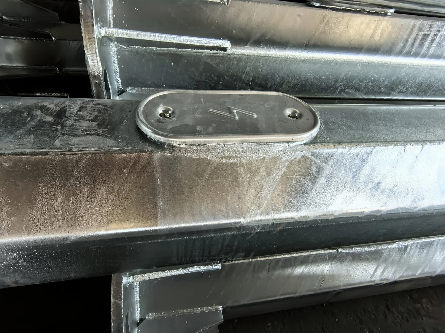
Check the base plate, fastening and cable-entry details together with the anchors and locating template. Give the relief, position and dimensions needed for the installer to confirm the equipment interface against the approved drawings. Where a foundation will be retained, obtain the field information and review that the project requires. Historic reports for similar poles can help identify the questions to ask, while the released drawing and approval define what will be installed. Mark the controlled drawing revision so the civil team, supplier and receiving staff recognise the same arrangement.
Ask for the night operating hours and actual load in each mode, the expected solar conditions and reserve requirement, and the placement of the photovoltaic surface. Have the supplier identify the panel, controller, battery and enclosure used in that assessment. If two proposed variants serve the same road and hours, compare the estimated charging and recovery on the same basis and identify why their parts differ. If an alternate option uses a different light output or schedule, show that difference explicitly. The comparison should preserve the owner’s required lighting and point to the assumptions that drive the supply decision.
Map the approved equipment and its circuits to the assembly drawings. Mark connector positions and where cable protection and site connections are required. Identify any local supply and fitting responsibilities at the site. If a larger panel, new battery or revised enclosure is proposed, look at the parts, cable, working clearance and lifting implications alongside the charging result. Ask the contractor where the system will be reached later and whether maintaining one component needs access to another. Use these answers to decide whether the whole option improves the project or shifts a problem elsewhere.
Use a review date and a version for the index. List the references for lighting, energy, pole and foundation, wiring, drawings, sample and material list. Mark what will be checked before manufacture, where the owner must approve a change and what will first be assessed on site. A tender or pricing option can use provisional data at its proper stage. Record what remains to be shown before it becomes an order or an instruction to build. Give the installer the released version when the approval is ready.
If the buyer chooses an alternative after checking both proposals, update the condition and difference list. A change in panel can require a revised equipment position and structural assessment. A changed optic or profile can require a review of performance and energy. A changed civil detail can affect fittings or cable entry. Record each affected part and document with the person handling the review. Keep accepted items in the master list rather than reopening them unnecessarily. This allows the site team to see why the parts being delivered differ from an earlier sample or budget proposal.
At the first installation, verify that the supplied parts, approved drawings and site conditions go together. Have the responsible parties check installation and service access at a representative position. Confirm the cable organisation and controller operation using the equipment instructions. Arrange the road and operating checks specified for the site, and identify the day and night procedures needed to review lighting and charging. Keep the equipment and settings for the tested position identifiable. If the alignment or installation changes, update the position record and the relevant review data before releasing the repeated work.
Make the spares and maintenance list follow the same approved versions. Where the road uses two panel assemblies or multiple optics, identify the matching spare by position and keep the relevant drawings on file. Ask the operator to define who approves a replacement that changes the mounting, fit or electrical programme. When the supplier’s original component is eventually replaced by a successor, compare it against the accepted interfaces and service requirements. The team can then check the relevant assumptions without reopening the complete road project.
Give the owner an installed equipment list by pole ID and a copy of the accepted drawing and settings references. Mark the applicable optic and replacement items and note which assemblies differ. Record the responsible maintenance party and the information they will need to obtain compatible parts after the original order is complete. If an enclosure, panel or bracket later changes, use the controlled drawings to check which physical and performance assumptions should be reviewed. The approval index then becomes the starting point for a repair or extension instead of a collection of documents without their original context.
Use the head and optic identifiers, panel and cabinet dimensions, attachment offsets and loads in the lighting, electrical and structural submissions. Keep project-specific foundation and earthing approvals with their responsible designers.
Ask the supplier to put quantities, exclusions, spares, unloading and site work on separate lines. Match the packing list and the delivery point to the actual RFQ and the final pole IDs.
Check the delivered mount, template and cabinet against the signed drawings before use. Agree the trial lighting and control checks, records, training and handover owner before releasing the remaining positions.
Start with the tender deadline, document list and intended delivery point. Include a shareable BOQ link or ask how to send restricted documents.
Send the contractor a packing schedule that connects the pole ID to the enclosure, anchors, template and cable package. At unloading, record the full kits and keep separately delivered foundation items visible to both teams. Use the same IDs on the inspection record and the as-built schedule so maintenance can trace parts to the installed assembly.
Agree what can be reviewed provisionally and what depends on the loaded assembly. Provide the expected equipment geometry and site basis and confirm how changes will be handled. Bring the selected panel, bracket and other attachments into the engineering review before the responsible party releases construction information.
Ask which equipment, output and operating modes changed. Have the reviewer check the applicable optical and energy evidence, then confirm whether the mounting, loads or components were affected. Record the approved revision against the ordering and installation list. Keep the relevant earlier evidence with a clear scope when it continues to apply.
Use location IDs to identify which geometry and requirements apply to each. The same supplier can offer separate equipment and profiles where the duties differ. Keep each version with its corresponding lighting, electrical and structural references and use the location list to guide delivery, inspection and spares.
Send the approved civil drawing and field survey to the responsible reviewers. Confirm the actual positions, cable route and foundation information against the selected pole assembly. Review any necessary change through the project’s engineering process. Keep the records with the installed locations so future maintenance can trace the final arrangement.
Include the current road drawing, dimensions, site conditions, requested modes and acceptance criteria, and any fixed pole or foundation information. Give the project team a named contact for the equipment, pole and civil approvals. Ask the supplier to identify the files that apply to its option and the information needed to finish the remaining checks.
Set the daytime and nighttime checks in the site acceptance plan. Use the relevant daylight conditions to verify charging and controller operation. Assess the specified road performance at the agreed night conditions and modes. Record the remaining work with a responsible person if the tests take place on different dates.
Review the lamp and enclosure separately. For the enclosure include the cable entries, closures and installation arrangement in the approval and first-site inspection.
Record what changed, the revised drawing and approval, the affected poles and any site checks or calculations repeated after the change. Give the maintenance team the installed part numbers.
Use the approved final equipment arrangement and the site-specific structural and foundation design. Check that the base plate, anchors and conduit refer to that same revision.
Send the road and pole drawings, lighting schedule, civil status and separate panel, bracket and equipment choices already being reviewed.
WhatsApp us