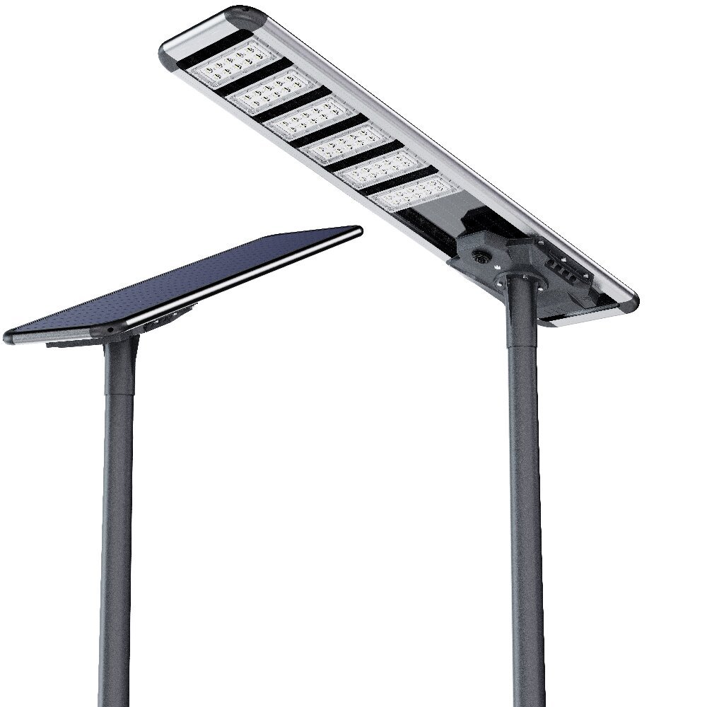
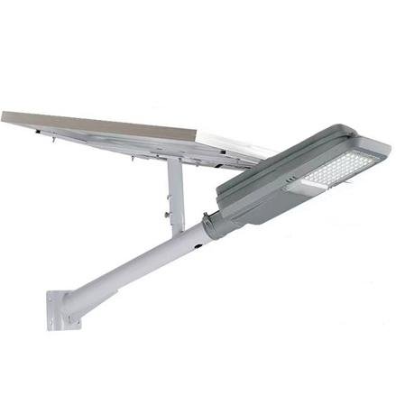
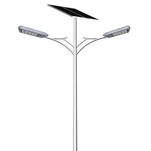
Part I — Executive Overview
The 3.2V Low-Voltage Architecture is a configuration option for reviewing conversion losses, protection design, and operating life for modern solar street lighting systems.
By matching the typical LED forward voltage range and using a 3.2V nominal LiFePO₄ battery, the system can reduce unnecessary voltage conversion, lowering thermal stress and improving reliability.
In practical engineering designs, this architecture can support 3 m to 12 m pole heights, especially when combined with:
- LED/luminaire efficacy verified for the offered configuration (230 lm/W is an illustrative calculation input here)
- Dual-controller arrangements sized for the actual load (80W is the calculation example below)
- LiFePO₄ Battery Packs (3.2V nominal)
- MPPT charging + smart load management
Note: Actual efficiency and output depend on driver topology, wiring design, component selection, operating temperature, and load strategy.
Part II — System Architecture Overview
Block Diagram — 3.2V Direct-Drive Solar Lighting System
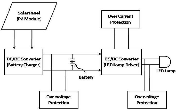
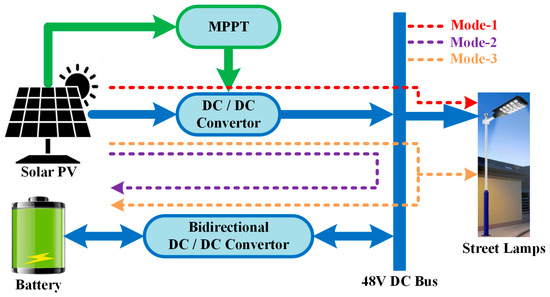
PV Module → MPPT Controller → 3.2V LiFePO₄ Battery → LED Driver → LED Module
↘ IoT / Sensors / Communication
Part III — Engineering Rationale
3.2V Nominal Battery Voltage and LED Driver Selection
- White LED forward voltage (typical): 2.7–3.3V
- LiFePO₄ battery voltage (nominal): 3.2V
Design check: LED current regulation must work across the full battery voltage range and temperature range. Similar nominal voltages do not establish a safe direct connection or constant light output.
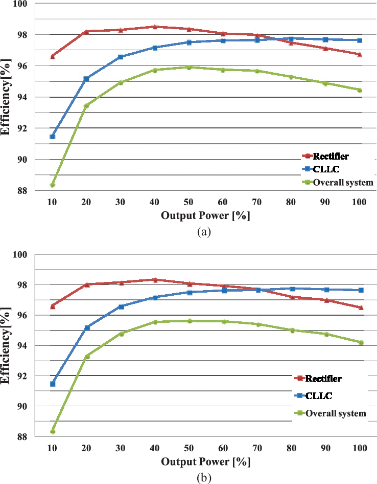
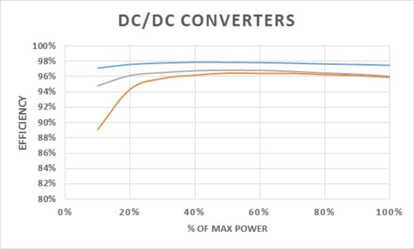
Illustrative Conversion-Efficiency Comparison
| Architecture | Conversion Path | Driver/Conversion Efficiency | Total System Efficiency* |
|---|---|---|---|
| 3.2V | None (direct-drive oriented) | 95–98% | 95–98% |
| 12.8V | Buck → LED | 90–93% | 85–88% |
| 24V | Buck → LED | 85–90% | 80–85% |
*These ranges are illustrative estimates, not measured ratings for all Sunlurio products or evidence that one voltage is always more efficient. Define the measurement boundary and compare controller, driver, wiring, and auxiliary losses at matched load and temperature; photovoltaic and battery charge/discharge losses are not established by this table.
Part IV — Safety & Compliance Framework
SELV Design Review (IEC 60364-4-41, Where Applicable)
3.2V is far below hazardous DC voltage thresholds, supporting a low-voltage safety design review. Nominal voltage alone does not establish SELV compliance. Verify separation, insulation, installation conditions, and the applicable requirements. Battery short-circuit current can still cause fire, burns, and connector damage; qualified electrical design and protection are required.
Battery Compliance (Common References)
- IEC 62133-2
- IEC 62619
- UN38.3
- MSDS
- UL1642 (optional / project-dependent)
BMS Required Protections
- Overcharge
- Overdischarge
- Overcurrent
- Short circuit
- Temperature cutoff
- Cell balancing
LED & Driver Compliance (Common References)
- IEC 60598-1 / IEC 60598-2-3
- IEC 61347-1 / IEC 61347-2-13
- LM-79 / LM-80 / TM-21
Part V — Electrical Engineering Analysis
Voltage Drop (IEC 60364-5-52)
Formula: Vdrop = I × R × L
Small-load illustration, not the 80W configuration:
- I = 1.2–2.8 A
- L = 1.2 m total conductor loop length (outgoing plus return)
- R (0.75 mm²) = 0.024 Ω/m
Estimated: Vdrop ≈ 0.08 V (≈ 2.5% at 3.2V), using 2.8A. The 3% figure is an example design target, not a universal acceptance limit
80W current check: P/V = 80W / 3.2V = 25A before conversion losses. Current increases as battery voltage falls or losses are included. At 25A, the same illustrative 0.024Ω/m × 1.2m loop would drop about 0.72V and dissipate 18W. It cannot be used as a suitable cable design for that load. Size conductors, connectors, BMS, overcurrent protection, and controllers from maximum current, loop length, temperature, installation conditions, and minimum operating voltage.
Thermal Design Considerations
- Reduced or minimized DC-DC conversion loss
- Reduced switching heat
- Lower MOSFET stress
- Potentially longer lifetime and higher stability
Part VI — Photometric & Performance Modeling
LED Baseline
Formula: Φ = P × ηLED
Illustrative calculation (not a tested luminaire rating): 80 W × 230 lm/W = 18,400 lm
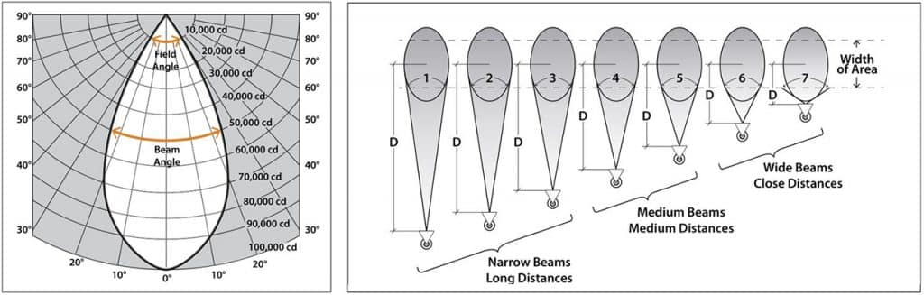
Illustrative Illuminance Calculation for 3–12m Pole Height
Table — Illustrative Average Illuminance (80W, assumed 230 lm/W)
These estimates use simplified beam areas and assumed utilization factors. They are not acceptance values or a model-matched IES/DIALux simulation. Verify complete-luminaire output, optical distribution, spacing, maintenance factor, and site criteria with the offered configuration.
| Height | Beam Diameter | UF | Avg Illuminance |
|---|---|---|---|
| 3 m | 6–7 m | 0.55 | 265–330 lux |
| 4 m | 8–9 m | 0.55 | 158–203 lux |
| 5 m | 10–11 m | 0.50 | 97–118 lux |
| 6 m | 12–13 m | 0.48 | 67–78 lux |
| 7 m | 14–15 m | 0.45 | 47–54 lux |
| 8 m | 16–17 m | 0.43 | 36–39 lux |
| 9 m | 18–19 m | 0.40 | 26–29 lux |
| 10 m | 20–21 m | 0.38 | 20–22 lux |
| 11 m | 22–23 m | 0.36 | 16–17 lux |
| 12 m | 24–25 m | 0.35 | 13–14 lux |
Part VII — Application Suitability
| Application Type | Illustrative Height Range | Design Review |
|---|---|---|
| Rural / Village | 3–6 m | Verify site photometry and autonomy |
| Urban Community | 6–9 m | Verify site photometry and autonomy |
| City Secondary Roads | 8–10 m | Verify site photometry and autonomy |
| Main Roads | 10–12 m | Verify site photometry and autonomy |
| Industrial Areas | 7–9 m | Verify site photometry and autonomy |
Part VIII — Mechanical & Installation Requirements
- Pole: Q235/Q345 steel, hot-dip galvanized
- Battery: LiFePO₄; confirm the applicable battery standard and configuration-matched test evidence
- Controller enclosure: IP65
- SPD: select coordinated protection for the site exposure and circuit ratings; 10kA is an example input, not a universal specification
- Wiring: calculate cross-section from maximum current, temperature, and voltage drop. 0.75 mm² belongs only to the small-load illustration above, not an 80W battery circuit
Part IX — Procurement Guidelines
The listed standards are references to evaluate against the intended product and market. Request matching reports and declarations; listing a standard or an MSDS/SDS is not a product certification claim.
Documents to Review for the Offered Configuration
- LM-79 Report
- LM-80 + TM-21
- IEC 62133-2
- UN38.3
- Controller schematic
- Mechanical drawings
Factory Acceptance Tests (FAT)
- Open-circuit voltage
- Load test
- Thermal test
- Charging curve verification
- Runtime testing
Part X — Final Engineering Conclusion
A 3.2V architecture, selected LED module, and dual-controller arrangement should be evaluated for:
- Measured conversion efficiency at the specified operating conditions; 95–98% is an illustrative range above
- Reduced conversion loss and thermal stress
- Strong alignment with LED forward voltage
- SELV-oriented safety design
- Configuration-matched photometric design for the intended pole height; 3–12 m is a planning range, not a performance guarantee
Select the architecture only after current, cable loss, battery protection, thermal behavior, autonomy, and lighting calculations have been reviewed. See the battery cycle-life evidence guide and maintenance-factor tender guide.