
Choose where the battery and controller will sit on a 7 m split solar street light. Compare cable paths, access requirements and the work a technician will need to do later.
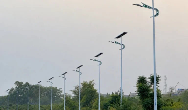
Show which side of the pole the crew can reach. At the first installation, check the box position, cable labels and controller settings before repeating the layout.
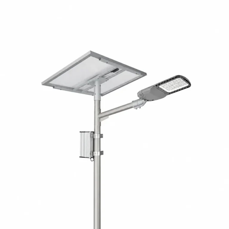
120 Wp separate panel · 1,024 Wh nominal battery in the series reference
Review enclosure height and cable run alongside the proposed 60 W head and the lighting grid.
Send first
Send the road plan, the side from which the crew can reach the enclosure, a marked cable route, and the tools or access equipment available on site. Identify who signs off the first pole.
What to check
Use the 60 W split reference to discuss the enclosure, cable and controller layout. The published Thailand project helps explain coordination at this height. Use the drawings and parts for your own order to check fit.
Choose a representative pole with the normal enclosure, cable run and panel location. Use the 60 W SL-SPL-HC candidate for a configuration review. The separately published Thailand case shows a project at this height. Its most useful lesson for a new site is to agree what the first complete pole must prove and who can release the rest.
| Stage | What the installation team records |
|---|---|
| Before lifting | Match the bracket and enclosure drawings to the kits, then label the head, PV and battery connections by the approved diagram. |
| At first power-up | Record the controller version and schedule, cable labels and the status checks specified in the installer instructions. |
| After dusk | Confirm the planned switch-on and dimming steps and view the road from the positions in the brief. Record any changes against the first pole ID. |
Give the installer and the maintenance lead the same marked-up record. Put a date and revision on the working schedule before it is copied to the remaining poles. For a remote installation, agree who takes the photos, who reviews them, and which settings the crew should retain for handover.
| Order item | Confirm in your BOQ |
|---|---|
| Lamps | Confirm the 60 W head, optic and arm for each lighting direction. |
| Solar and wiring | Specify panel bracket, battery box, controller, cable lengths, entries and connectors. |
| Pole and site work | Confirm whether the quote includes the pole, base, anchor kit and template. Agree who commissions the first installed pole. |
Sunlurio supplied 430 sets of 60 W split lights with 7 m conical poles in 2024 and provided remote installation guidance. For a similar order, use the first pole to approve the battery enclosure position, cable labels and controller settings before the crew repeats the installation.
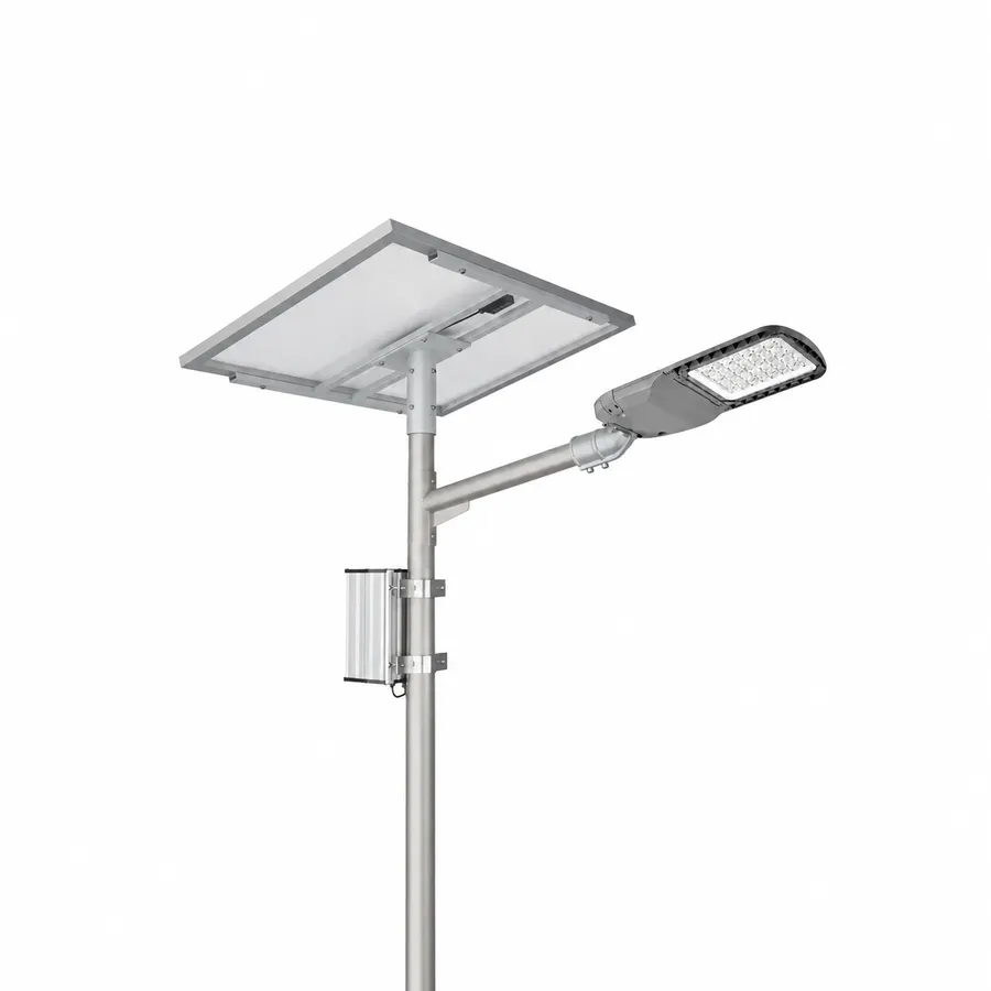
A 7 m lighting plan can look ready to order before anyone has drawn where the battery goes. A split system gives you room to place the panel and luminaire independently, and a separate enclosure may be placed below the panel or lower on the pole when the selected design allows it. Mark the enclosure on the site plan before choosing the supporting hardware. Ask who will service it, what access equipment they have and how often access is likely. A location the installer can reach during construction may be difficult for the owner to attend after traffic or site operations start.
Walk the route with the maintenance team and mark positions where a service vehicle can stop and where a gate or landscaping restricts access. At a busy site, a scheduled lane closure can change the cost of a task as simple as replacing a controller. An accessible lower position can reduce work at height, while exposing the enclosure to water, accidental impact or unwanted access. Compare those trade-offs with the actual placement, opening clearance and route to the load. Consider special positions separately when one arrangement will work for most of the project.
Ask for a section or elevation showing the battery, controller, cover, fixings, cable entries and the clear space available to withdraw the parts. Identify which enclosure holds which components if there are multiple boxes. If the battery is underneath the panel, show how the cover opens relative to the bracket and nearby luminaire arm. If the enclosure is lower on the shaft, mark its door orientation and working side in relation to the road. Give the field technician a way to see the equipment identifiers before taking apart other components.
Ask the supplier to tell you what can be replaced separately for the proposed equipment. The controller, battery and connectors can require different procedures and matching settings. Compare the supported replacement parts and the tools or equipment needed to access them. If replacing a common part requires dismantling the solar panel, ask whether a different cover direction or mounting arrangement is available for review. Trace that access decision back to the layout and parts list. A small drawing change can matter more to the service team than a difference in the external look of the finished pole.
A cable path sketch should show each circuit from the source to the relevant connection, including the photovoltaic module to the controller and the battery and controller to their respective points. Mark the connector positions, protected runs, openings into the pole, limits on bending, and where spare length will sit. State which circuits and covers must be managed when a component is removed. Use the selected supplier’s wiring and installation instructions with qualified site staff, especially when circuits may be energised during service. Give the installer a labelled drawing they can carry to the pole.
Tell the electrical reviewer the actual distance travelled by the conductors along the route. Changing the battery from a position under the panel to a lower position can add length to one circuit and shorten another. It can affect cable size, termination, the electrical checks and the position of protection. Ask the supplier to assess these choices for the actual current, voltage range and configuration. Keep the physical project sketch and the electrical schedule together. A cable approved for one arrangement may need a different length or termination when the enclosure moves.
List the luminaire, photovoltaic panel, battery enclosure, brackets and any other attachments with their positions. The drawing should show the light-emitting centre, which belongs in the lighting calculation, and the panel orientation, which belongs in the charging review. If there is a service door, identify which side it faces and what serves as the cable entry. Ask the pole and foundation reviewer to use the selected components and their loads. This matters when choosing a larger solar panel or adding another enclosure after the first pole drawing has been prepared.
Check the routes where internal welds, brackets or separate poles make cable access difficult. On a retained shaft, use the existing drawing and a field survey to identify available openings and the condition of the pole. A proposed cable path may pass through an area that is inaccessible after the base is installed. Ask when equipment will be fitted and when the cable can be drawn without removing parts. Agree which party verifies openings and the connection between the poles, equipment and foundations before the supplier releases repeat assemblies.
For the lighting task, state the road or site width, the proposed luminaire height and aim, spacing and the hours when the intended level must be delivered. Confirm the photometric file for the selected head. An independent panel arrangement lets you change the lamp position without changing where the panel points, subject to the allowed mounting and electrical arrangement. If you choose a different head or operating setting after the layout is reviewed, ask which photometry, wiring and battery assumptions have changed. Document the revision before comparing runtime or placing repeat orders.
For the charging check, show the panel location, angle and shading conditions at the time of year that most affects the required service. Request usable battery energy and the actual lighting schedule, including any reduced mode or sensor period. If the battery is proposed near ground level, ask how the location affects its operating environment, protection and serviceability. Temperature and enclosure placement matter alongside the panel energy and electricity drawn overnight. Ask for the charge, discharge and storage limits separately. A cell that can be stored in a temperature range can have different limits for accepting a charge. Where the battery sits beneath the panel, ask how the housing temperature is assessed in the proposed conditions and which action the controls take at their limits.
At the first equipped pole, verify the contents against the approved bill of materials. Record the cable path as installed, panel direction and enclosure location. Have the installer open the relevant cover and show where a controller or battery would be removed using the approved procedure. Ask the maintenance team whether they can bring the planned access equipment to the working position. If the installer finds a better route or cover direction, get the change reviewed and put the updated orientation and cable information on the drawing before the next pole is assembled.
Give the owner a record they can read at the site. It should identify the pole, applicable layout, luminaire and optic, panel, battery, controller, operating programme and access instructions. Keep the verified compatible spares tied to their fitted configurations. Mark any positions with a different enclosure or programme. At night, confirm operation under the agreed settings and log the mode used for the lighting check. At an appropriate time in daylight, confirm that the approved procedure shows charging behaviour as expected. Record defects and corrections while the supplier and installer can still match them to equipment.
For a 2024 road and public-area project in Thailand, Sunlurio supplied split lighting sets with 7 m conical steel poles and supported local installation through videos and remote guidance. A delivery like this is easier to install when the distributor and crew can identify the pole, bracket and system parts together. Ask which assembly records, connection drawings and video steps will apply to your own scope, and confirm who will be responsible for work on site.
Ask for drawings of the box, panel bracket and cable route, plus the controller schedule and head model. Check that these are the versions provided to the crew.
At first power-up check the installed labels, settings and cable route. At dusk, check the actual switch-on and dimming stages from the agreed viewing locations.
Give the field lead the first-pole photos and marked drawing. For a remote site, ask who will train local staff, receive fault photos and supply the agreed spares.
Before dispatch, decide what the field team will report if the light comes on late, stops early or skips the dimming step. Give each unit a pole ID and record the local time, site conditions, controller status and labels from that pole. The maintenance contact can then compare the fault with the approved settings and installed parts.
Look for a safe approach and room to open it with the necessary tools. Think about vehicle spray, standing water, impact and access by passers-by. Review the cable path and electrical design as part of the move. Compare those practical constraints with the access equipment needed for a higher location before choosing the layout.
List the common arrangement and any exceptions on the pole schedule. A position near a drainage channel or right beside a pedestrian crossing may need a different enclosure location even on an otherwise uniform project. Document the associated cable and support changes with the particular poles and confirm that the chosen equipment is compatible.
Give a drawing showing the entries, protected path, connector positions and when connections are made relative to pole assembly. Ask the installer to confirm that the route is physically clear. If a replacement cable is likely to need the same route, agree how they can access both ends. Label cable circuits and identify where the final as-built route gets recorded.
Check the enclosure dimensions, cable entry, protection requirements and physical fixing. Compare the proposed electrical parts against the selected lamp, panel and battery, including connections and supported settings. Agree which party confirms compatibility and carries out commissioning. If the buyer has a preferred local source, review the specific part and documents before the ordering schedule is closed.
Send the pole elevation or a marked site photograph, the equipment you expect to mount and the position of nearby obstructions. Identify the working side, local weather concerns and access equipment available to the maintenance crew. Add the proposed operating hours and the preferred battery position if known. These details help the team decide whether to adjust the enclosure, cable route or mounting hardware first.
Ask for the panel bracket, cable entry, controller or battery label and enclosure access. Add a full view with the pole number so the photos can be traced to the installation check.
Yes. Shipping checks confirm the listed equipment and its condition. Commissioning must also confirm charging, the selected mode and operation at the site. Keep those results with the pole number and the planned handover records.
Keep the equipment labels, cable schedule, controller setting record and the corrected enclosure photo. Keep the responsible technical contact with the same file so a later fault can be traced to the installed version.
Send a site sketch, light height, your proposed battery location and the access equipment available for the service team.
WhatsApp us