SL-AIO-HC All-in-One Solar Street Light Series
40–150 W integrated solar street lights for municipal roads and public areas, with project-matched battery capacity, optics and engineering support.
Start with road width, pole height, spacing, operating hours and autonomy—not LED wattage alone.
SL-AIO-HC Series at a Glance
40–150 W
25.6 V
100–300 W
LiFePO₄
MPPT
200 lm/W
High-efficacy options depend on the selected LED package, optic, CCT and operating conditions. Confirm the applicable photometric data before using them in a lighting calculation.
Project Inputs for Model Selection
Share these conditions before quotation. They determine the model, PV/battery sizing, optics and operating profile.
Missing road geometry or operating data can lead to the wrong model, battery size or optical selection.
SL-AIO-HC Model Comparison
Use the table to shortlist one or two models. Final selection still depends on the road layout and operating profile.
Common battery voltage: 25.6 V.
| Model | LED power (W) | PV power (W) | Nominal battery energy (Wh) | Equivalent capacity (Ah) | Reference luminous flux (lm)* | Body L × W × D (mm)** |
|---|---|---|---|---|---|---|
| SL-AIO-HC-40 | 40 | 100 | 384 | 15.00 | 8,000 | 1000 × 500 × 50 |
| SL-AIO-HC-60 | 60 | 120 | 576 | 22.50 | 12,000 | 1200 × 500 × 50 |
| SL-AIO-HC-80 | 80 | 150 | 665 | 25.98 | 16,000 | 1500 × 500 × 50 |
| SL-AIO-HC-100 | 100 | 220 | 1,331 | 51.99 | 20,000 | 1500 × 700 × 50 |
| SL-AIO-HC-120 | 120 | 250 | 1,715 | 66.99 | 24,000 | 1500 × 750 × 50 |
| SL-AIO-HC-150 | 150 | 300 | 2,329 | 90.98 | 30,000 | 1600 × 850 × 50 |
SL-AIO-HC-40
- LED power
- 40 W
- PV power
- 100 W
- Nominal battery energy
- 384 Wh
- Common voltage
- 25.6 V
- Equivalent capacity
- 15.00 Ah
- Reference luminous flux*
- 8,000 lm
- Body L × W × D**
- 1000 × 500 × 50 mm
SL-AIO-HC-60
- LED power
- 60 W
- PV power
- 120 W
- Nominal battery energy
- 576 Wh
- Common voltage
- 25.6 V
- Equivalent capacity
- 22.50 Ah
- Reference luminous flux*
- 12,000 lm
- Body L × W × D**
- 1200 × 500 × 50 mm
SL-AIO-HC-80
- LED power
- 80 W
- PV power
- 150 W
- Nominal battery energy
- 665 Wh
- Common voltage
- 25.6 V
- Equivalent capacity
- 25.98 Ah
- Reference luminous flux*
- 16,000 lm
- Body L × W × D**
- 1500 × 500 × 50 mm
SL-AIO-HC-100
- LED power
- 100 W
- PV power
- 220 W
- Nominal battery energy
- 1,331 Wh
- Common voltage
- 25.6 V
- Equivalent capacity
- 51.99 Ah
- Reference luminous flux*
- 20,000 lm
- Body L × W × D**
- 1500 × 700 × 50 mm
SL-AIO-HC-120
- LED power
- 120 W
- PV power
- 250 W
- Nominal battery energy
- 1,715 Wh
- Common voltage
- 25.6 V
- Equivalent capacity
- 66.99 Ah
- Reference luminous flux*
- 24,000 lm
- Body L × W × D**
- 1500 × 750 × 50 mm
SL-AIO-HC-150
- LED power
- 150 W
- PV power
- 300 W
- Nominal battery energy
- 2,329 Wh
- Common voltage
- 25.6 V
- Equivalent capacity
- 90.98 Ah
- Reference luminous flux*
- 30,000 lm
- Body L × W × D**
- 1600 × 850 × 50 mm
* Reference flux
Reference luminous flux is calculated from rated LED power using the nominal 200 lm/W basis. Use the photometric file matched to the selected model and optic for lighting calculations.
Battery capacity
Nominal battery energy is listed by model. Equivalent Ah is calculated at 25.6 V.
** Dimensions
The listed dimensions cover the lamp body only. The 50 mm depth does not include the mounting bracket.
System Architecture & Serviceability
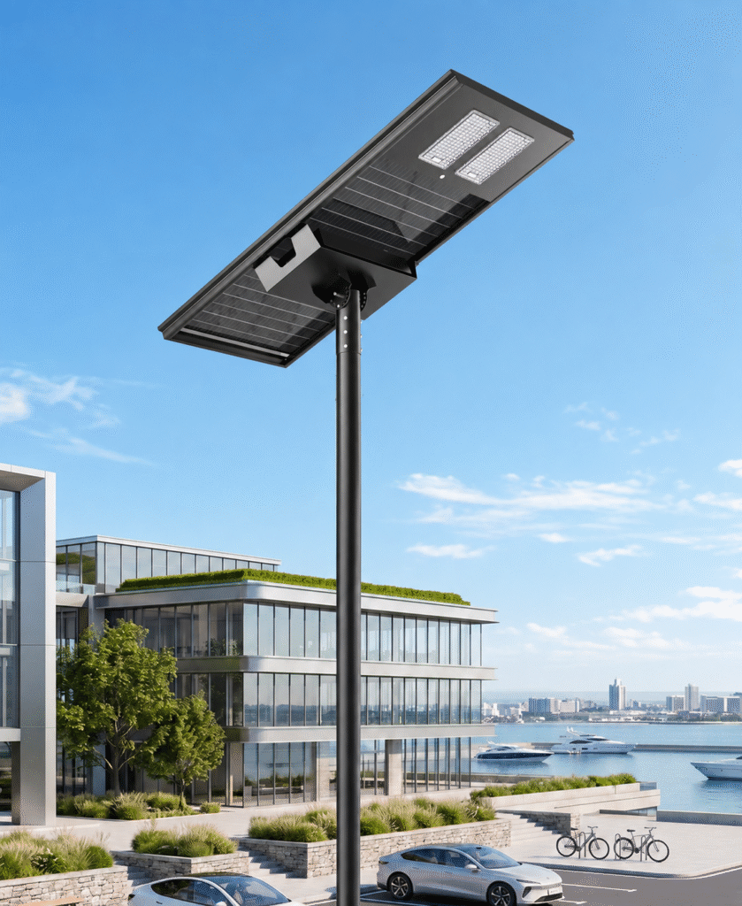
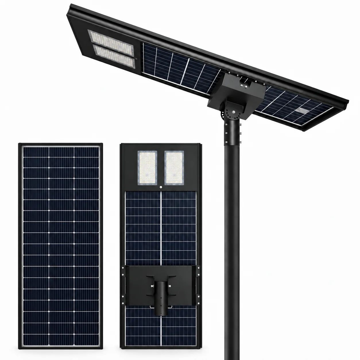
The SL-AIO-HC combines the solar panel, LiFePO₄ battery, controller and LED/optical system in one luminaire. Service access matters as much as initial installation.
LED Module & Optics
Choose the LED package and optic together; output alone does not determine the road-lighting result.
LiFePO₄ Battery
Battery energy is matched to the nightly operating profile and autonomy target. Nominal Wh is listed by model.
PV & MPPT Charging
PV power and MPPT settings are checked against the battery system and local solar conditions.
Serviceable Architecture
A removable battery pack and quick-connect arrangements make component access and replacement easier.
Operating Profile & Energy Balance
Autonomy cannot be judged from battery Wh alone. Review the nightly operating schedule, dimming stages, usable battery energy and local solar conditions together.
| Design input | What is reviewed |
|---|---|
| Nightly operating profile | Operating hours, power settings by time period, sensor behaviour and the minimum required lighting level. |
| Battery energy | Nominal energy, the permitted usable range, conversion losses and the selected battery protection settings. |
| Solar replenishment | Seasonal solar conditions, shading, panel orientation and the electrical compatibility of the selected PV and controller. |
| Autonomy target | The agreed low-solar operating scenario and the required output during each stage. |
A 12-hour operating requirement does not necessarily mean 12 hours at full rated LED power. Autonomy still depends on usable battery energy, dimming and local solar conditions.
Review solar lighting dimming design when defining the operating profile.
Lighting & Optical Configuration
Higher wattage does not automatically produce better road lighting. The optic, photometric file, mounting height and pole spacing must work together.
| Standard nominal luminaire efficacy | 200 lm/W. |
|---|---|
| High-efficacy project options | 210–230 lm/W, according to the selected LED, optic and operating conditions. |
| LED packages | 3030 / 5050 / 5054 / 7070, according to configuration. |
| Standard CCT | 6000 K. |
| CCT options | 3000 / 4000 / 5000 / 6500 K. |
| Colour rendering index | Ra ≥70. |
| Optical distribution | Type II / Type III / Type IV, selected for the project layout. |
| Photometric files | IES / LDT matched to the selected model, optic and output setting. |
For optic selection, review road-lighting optics and beam patterns.
Nominal efficacy and calculated reference flux are not substitutes for model-specific photometric data. Lighting calculations use the file matched to the selected configuration. One generic IES / LDT file does not represent every model.
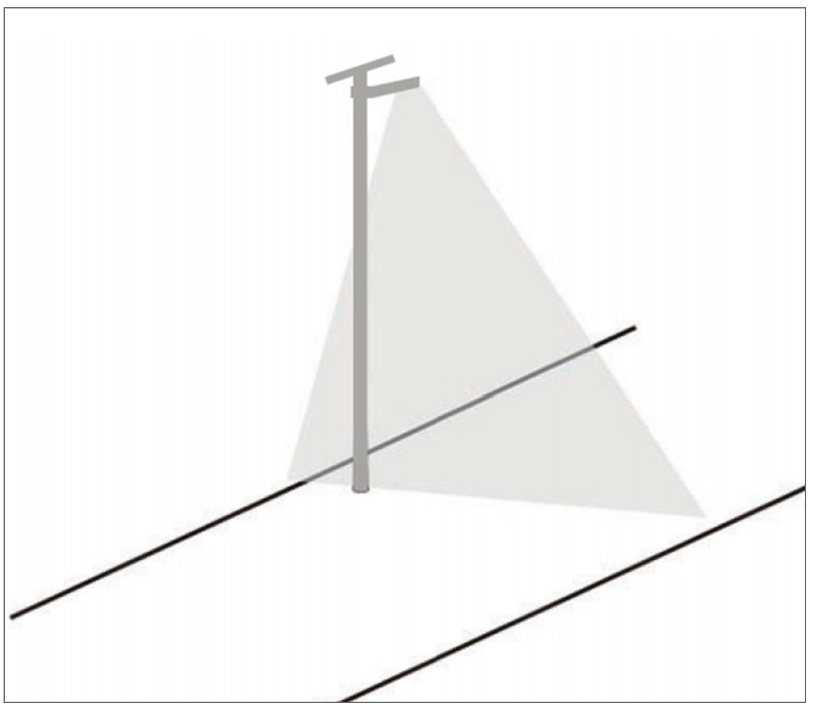
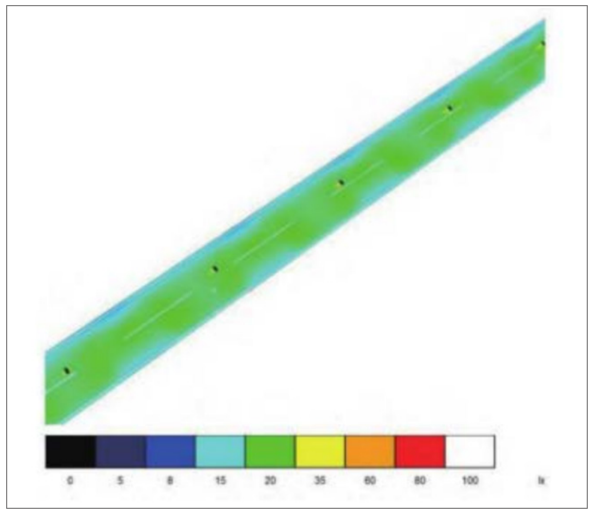
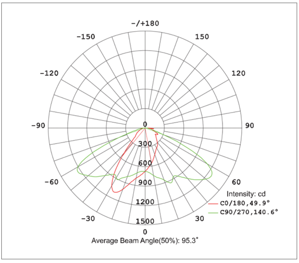
Lighting Distribution
These diagrams are reference illustrations from the product source material, not HC model-specific photometric results. Final calculations use the IES/LDT file matched to the model and optic.
Road Lighting Design Review
Before preparing a road-lighting calculation, confirm the road section, luminaire arrangement, mounting height, pole spacing and target lighting class. Without these inputs, the assessment may not represent the actual road.
| Review item | Information required | Evaluation/output |
|---|---|---|
| Design basis | Information requiredCountry of installation, road use, applicable standard and lighting class. | Evaluation/outputAgreed criteria and method for the lighting calculation. |
| Road geometry and arrangement | Information requiredCarriageway and footway widths, pole arrangement, mounting height, spacing, outreach and tilt. | Evaluation/outputLayout and geometry used in the calculation. |
| Illuminance | Information requiredIlluminance evaluation area and applicable criteria. | Evaluation/outputAverage and minimum illuminance (lux), as required by the project method. |
| Road-surface luminance | Information requiredApplicable road class, pavement assumptions and observer/evaluation conditions. | Evaluation/outputRoad-surface luminance (cd/m²) where applicable. |
| Uniformity | Information requiredDefined evaluation area, method and ratio. | Evaluation/outputWhere applicable, road-luminance overall uniformity is Uo = Lmin / Lavg. Any illuminance ratio is separately labelled Emin / Eavg with its evaluation method. |
| Glare | Information requiredApplicable road-lighting method and observer conditions. | Evaluation/outputTI or another applicable glare indicator when required by the project. |
| Photometric and maintenance basis | Information requiredSelected model, lens, output setting, IES / LDT identity and maintenance assumptions. | Evaluation/outputTraceable calculation basis for the confirmed configuration. |
This is a design checklist, not a verified HC lighting result. Photometric results are meaningful only when the luminaire, optic, output setting and installation geometry match the calculation inputs.
For a defined road layout, request DIALux lighting design support.
Mechanical & Installation
Before order release, confirm the pole interface, bracket angle and complete mounting envelope. The 50 mm value in the model table is lamp-body depth only.
Mechanical Parameters
| Housing | Aluminium structure; finish according to the selected configuration. |
|---|---|
| Body dimensions | Refer to the model comparison and outline drawings above. |
| Body depth | 50 mm, excluding the mounting bracket. |
| Mounting interface | Ø70 / Ø80 / Ø96 mm options with the matched bracket. Each interface is selected for its corresponding pole and bracket arrangement. |
| Tilt adjustment | 0–30°; final setting follows the installation drawing. |
| Ingress protection | IP66 standard; IP65 available as a specified option. |
| Impact protection | IK08. |
| Operating environment | −30 °C to +65 °C for the specified configuration; battery charging and discharging limits are checked separately. |
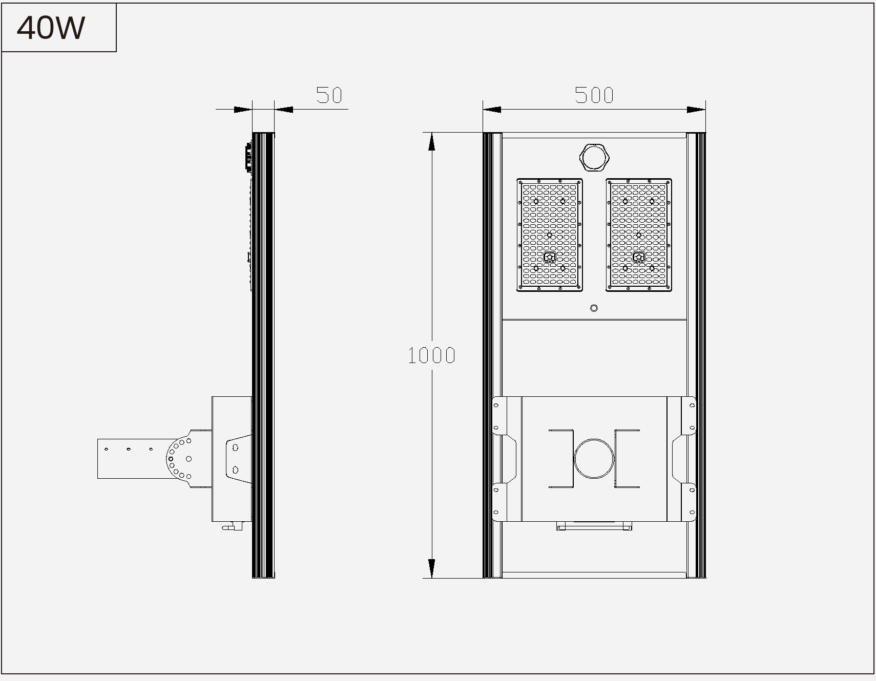
Dimensions & Outline Drawings
Compare the luminaire footprint in each outline and side view, then confirm the mounting envelope with the matched installation drawing. Dimensions are in millimetres; the stated 50 mm depth applies to the lamp body only and excludes the mounting bracket.
For project coordination, request datasheets and installation drawings for the selected model.

SL-AIO-HC-40
Luminaire body size: 1000 × 500 × 50 mm
View drawing
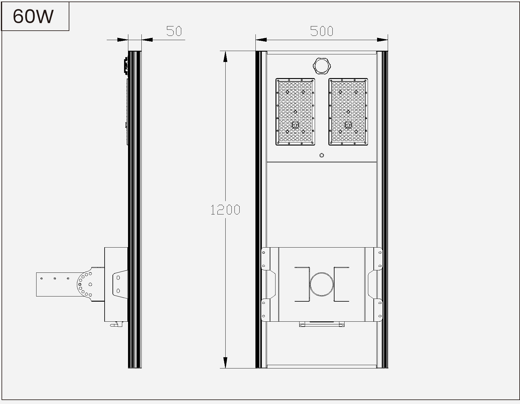
SL-AIO-HC-60
Luminaire body size: 1200 × 500 × 50 mm
View drawing
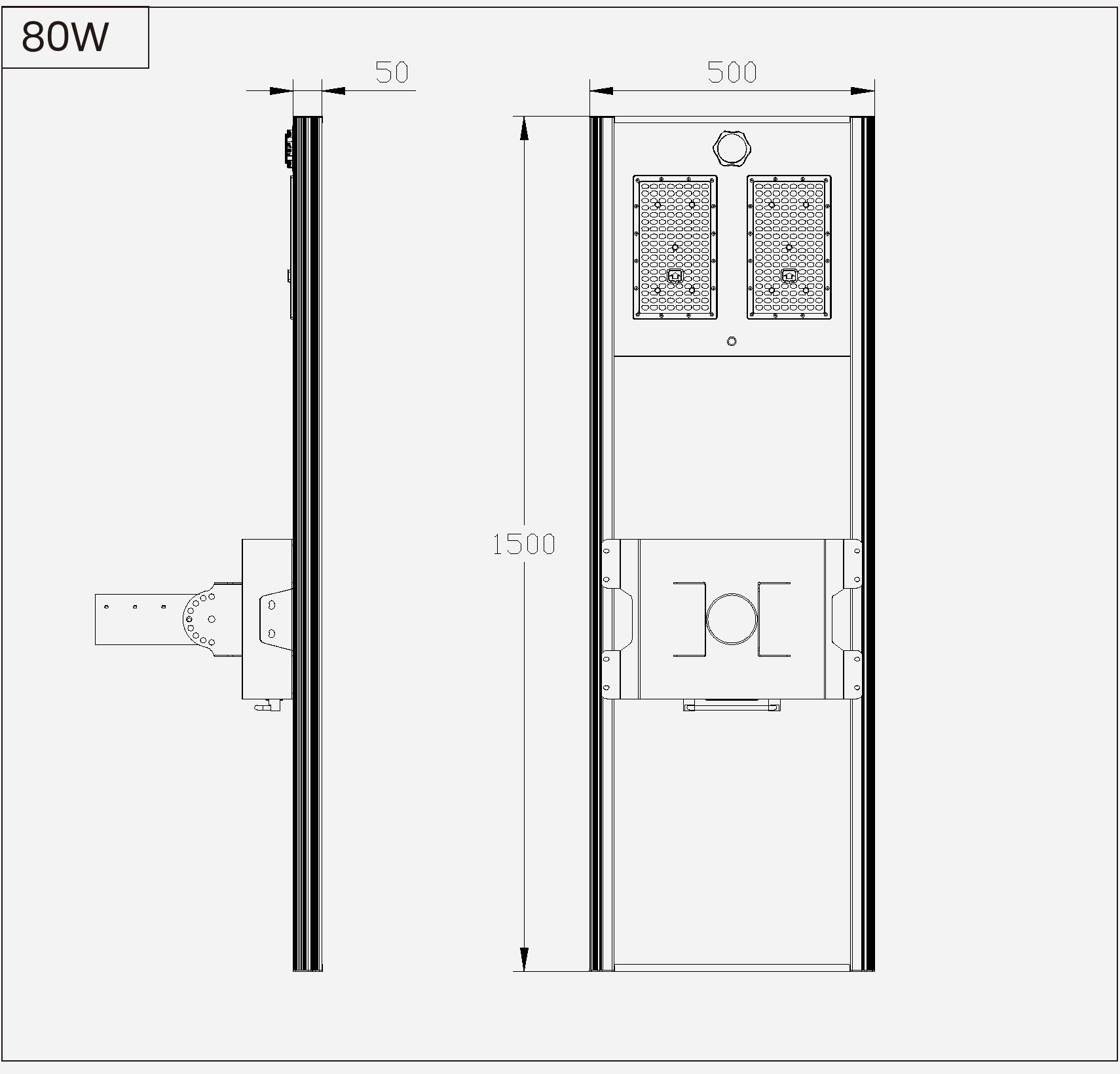
SL-AIO-HC-80
Luminaire body size: 1500 × 500 × 50 mm
View drawing
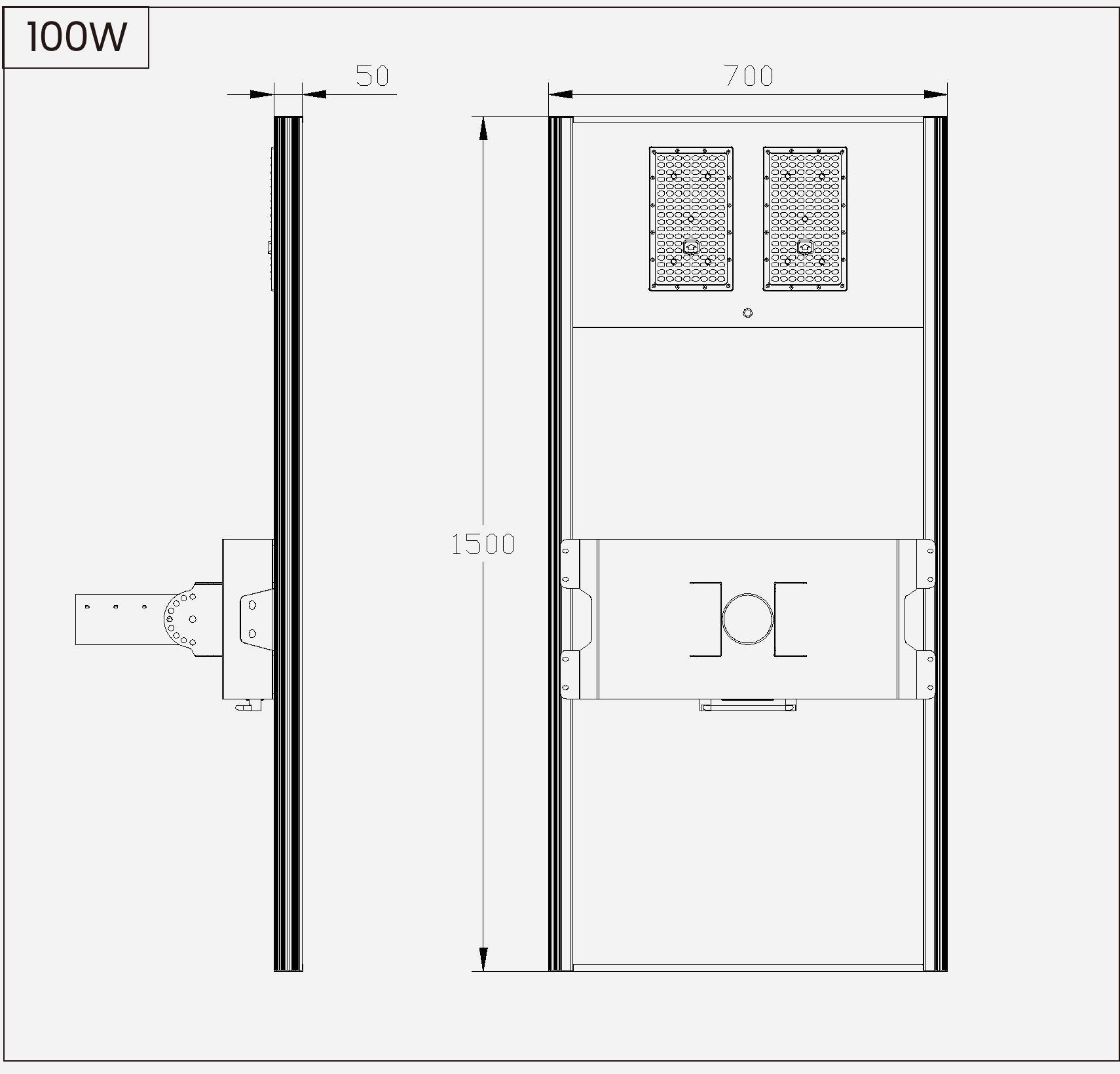
SL-AIO-HC-100
Luminaire body size: 1500 × 700 × 50 mm
View drawing
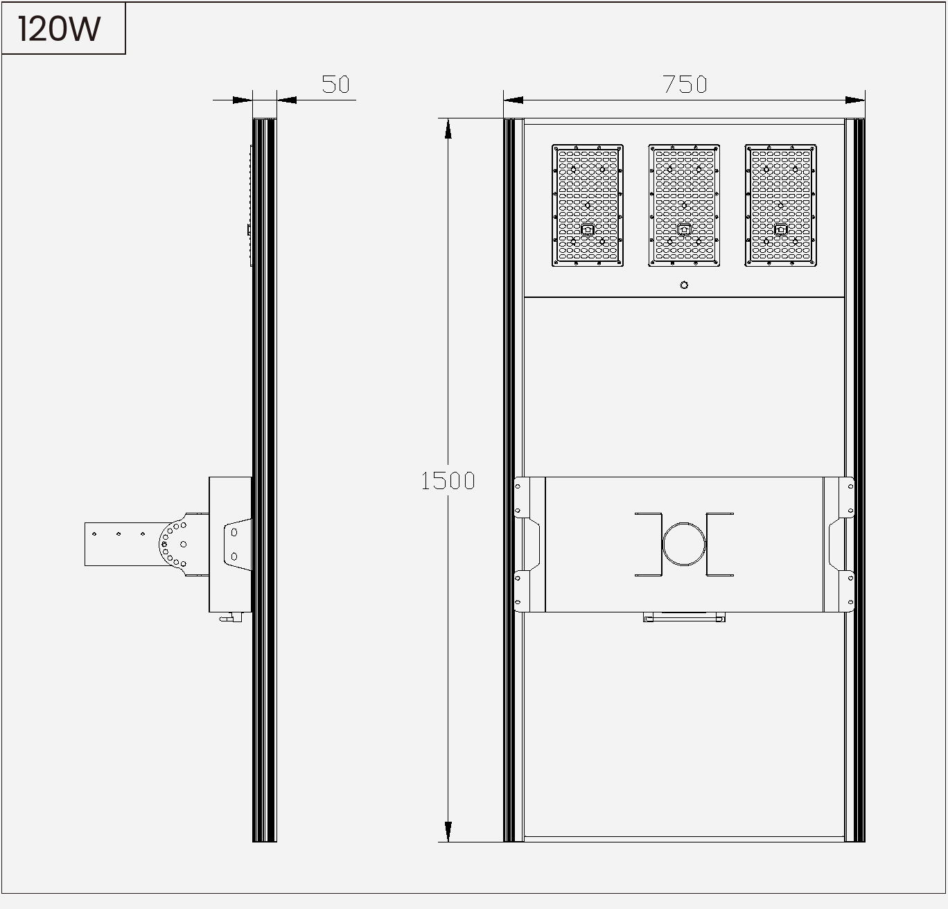
SL-AIO-HC-120
Luminaire body size: 1500 × 750 × 50 mm
View drawing
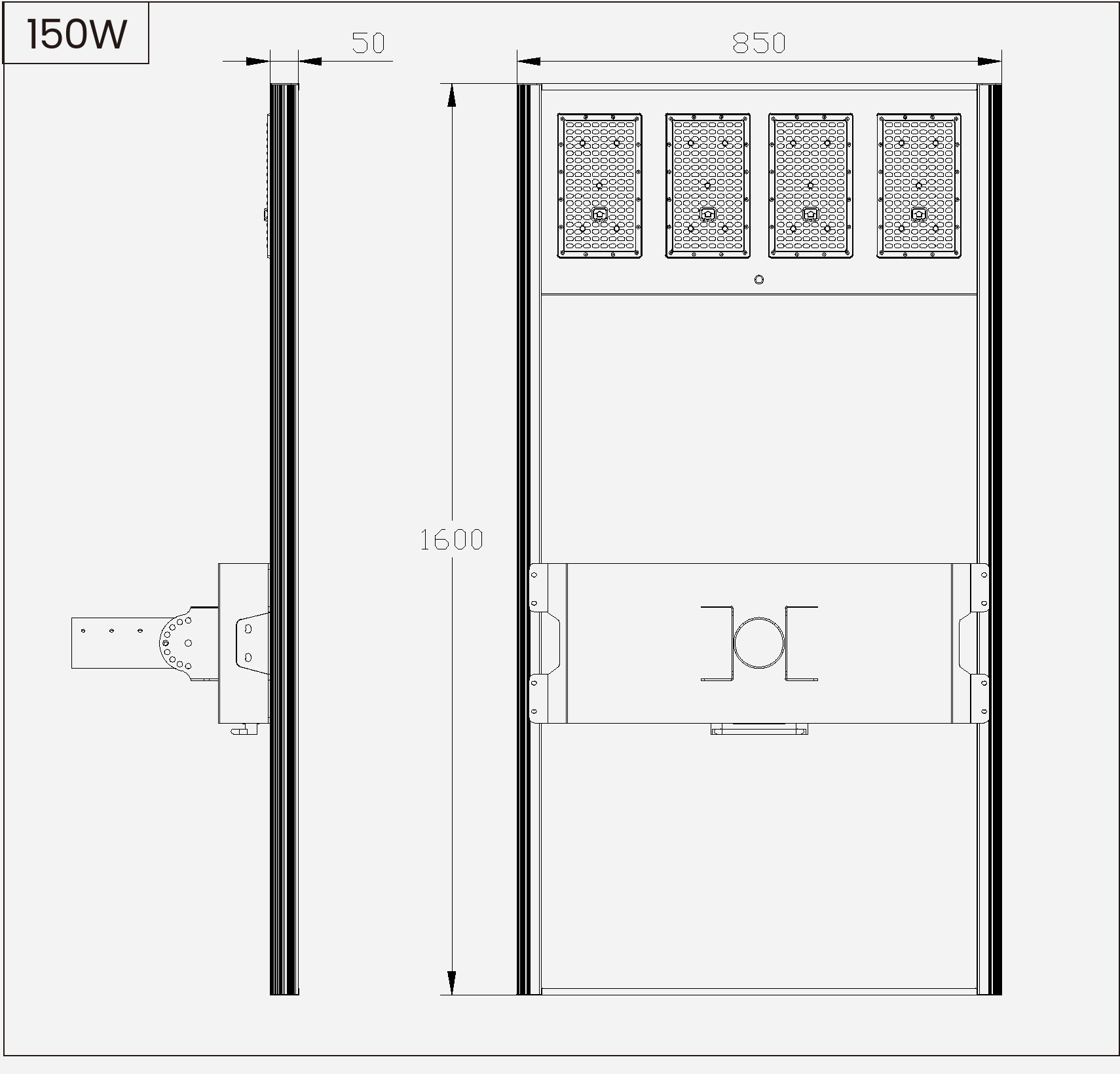
SL-AIO-HC-150
Luminaire body size: 1600 × 850 × 50 mm
View drawing
Reference outline drawings. Dimensions are in millimetres. The stated 50 mm depth excludes the mounting bracket; final installation details follow the matched model drawing.
Mounting Arrangement
The illustrations show the bracket-to-luminaire and luminaire-to-pole installation sequence.
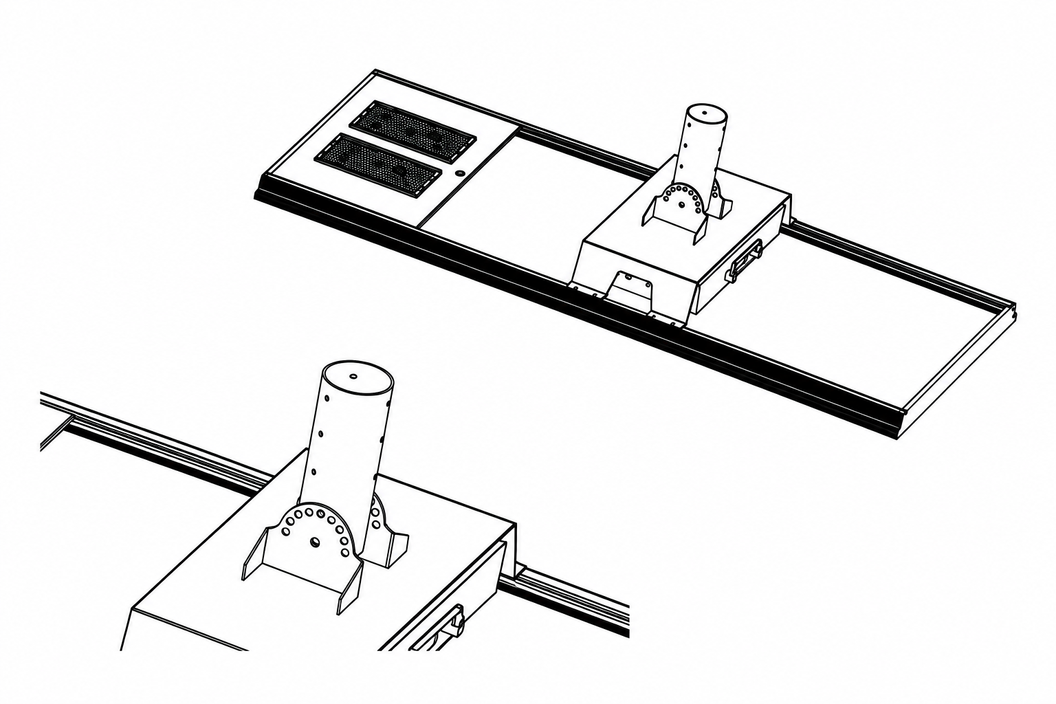
01 — Attach the Mounting Bracket
Fit the bracket specified for the luminaire and mounting interface.
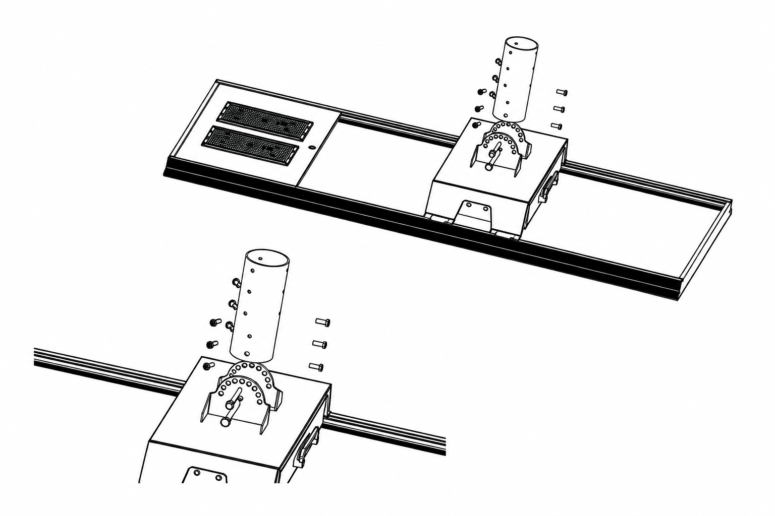
02 — Secure the Luminaire to the Pole
Check the pole interface, insertion depth, tilt setting and fasteners against the installation drawing.
Illustration only. Final mounting details follow the project drawing.
Engineering Documents & Tender Support
For consultant or tender review, request the files needed for the model and procurement stage.
Model-Matched Datasheet
Electrical, optical and mechanical data for the agreed specification.
Request Model-Matched Datasheet →IES / LDT Photometric File
Photometric data for the model, optic and output setting.
Request IES / LDT →DIALux / Layout Review
Lighting assessment using the agreed road geometry and design criteria.
Request DIALux Review →Drawings / BOQ Mapping
Dimensional coordination and BOQ/document matching for the agreed supply scope.
Submit Project / BOQ Requirements →File availability depends on the model, project inputs and procurement stage. Project drawings and technical files are supplied for the agreed scope. IES / LDT files, DIALux reviews, BOQ compliance matrices and certificate/tender packs remain controlled, request-based documents. For preparation, review model-matched IES / LDT files and BOQ matching and tender document review.
Packing & Project Delivery Planning
Container planning starts after carton size, gross weight, stacking limits and accessory scope are confirmed. Quotation-stage quantities remain planning values.
Packing Configuration
The packing arrangement follows the selected model and accessory scope.
Container Planning
Planning uses confirmed carton dimensions, gross weight and permitted stacking conditions.
Batch Consistency
Model labels, accessories and inspection records are checked against the agreed order configuration.
Container quantities are confirmed only after final packing, gross weight and loading conditions are agreed.
Manufacturing & Quality Evidence
See how the order is assembled, checked and documented before shipment.
Manufacturing & Assembly
Assembly is checked against the order specification and confirmed component list.
View ManufacturingPhotometric & Reliability Testing
Test records identify the product and test scope they cover, so results are not applied to unrelated configurations.
View Testing ProcessProject Documentation & Traceability
Datasheets, drawings, BOQ mapping and inspection records are kept together for the order and tender file.
View Engineering SupportSL-AIO-HC Frequently Asked Questions
How should a project choose among the 40W, 60W, 80W, 100W, 120W and 150W models?
Start with road width, pole height and spacing, required illuminance and uniformity, operating hours, dimming schedule, autonomy target and local solar conditions. Rated LED wattage alone does not determine the final model.
Is the 150W model automatically the right choice for higher poles?
No. Select the model using pole height together with road geometry, spacing, optical distribution, target illuminance and uniformity, and the PV/battery energy balance. A higher rated wattage is not a substitute for project lighting calculations.
Is 200 lm/W a measured result for every model?
No. The 200 lm/W figure is the nominal basis for reference luminous-flux calculations, not a measured result for every model. Evaluate actual lighting performance with the IES/LDT file matched to the model, optic and output setting.
Can the PV module and battery be customized for project conditions?
Yes, subject to engineering review. PV and battery capacity may be adjusted for local solar resource, operating profile, autonomy target, temperature range and approved component availability. Final values must be confirmed in the project configuration.
Are IES/LDT files and DIALux reviews available?
Yes. Model- and optic-matched IES/LDT files and a DIALux or layout review can be provided after project inputs and the configuration are confirmed. A generic photometric file should not be used for all models.
What warranty terms are available for the SL-AIO-HC series?
A five-year warranty is available subject to the agreed configuration, order scope and written warranty terms. Confirm the applicable terms in the project quotation and contract documents.
Does the stated 50 mm depth include the mounting bracket?
No. The 50 mm value refers to the lamp body only. Use the matched installation drawing to confirm the bracket, pole interface and complete mounting envelope.
Request SL-AIO-HC Project Configuration
Send the road layout, BOQ or project inputs to start a configuration review. We will check model selection, PV/battery sizing, optics and required documents before quotation.