
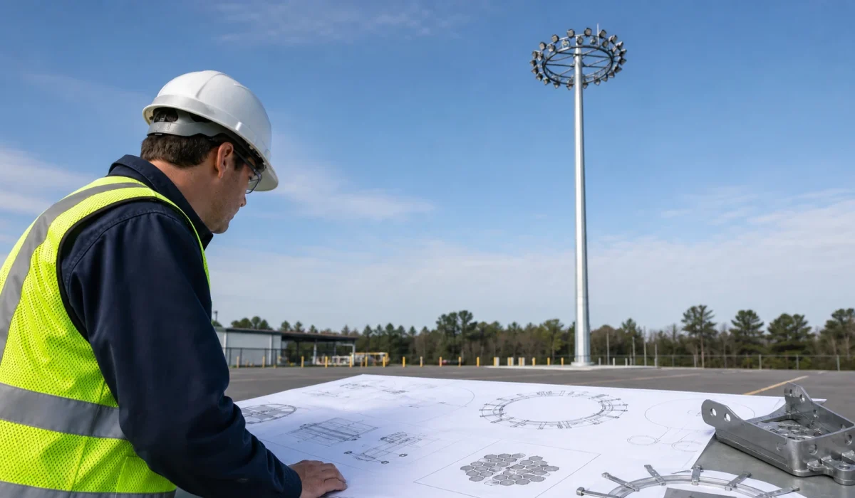
Quick Answer
High mast pole foundation size, anchor bolts, base plate thickness and wind-load resistance cannot be selected from pole height alone.
A 25m, 30m or 35m high mast pole does not have one universal foundation size. The correct foundation and base connection must be reviewed using project-specific wind criteria, soil and geotechnical data, pole reactions, luminaire weight, effective projected area, headframe configuration, anchor layout, local codes and qualified structural calculation.
Rules such as “foundation depth equals pole height divided by six” or “30m high mast pole equals one fixed concrete block size” are unsafe for formal EPC, municipal, highway, port, airport or industrial projects. They may help with rough cost discussion only when clearly marked as preliminary, but they should not be used for construction drawings, anchor bolt ordering or site installation.
A complete review should define:
- Governing code and edition.
- Wind-speed definition and design basis.
- Exposure or terrain category.
- Risk category or return period.
- Topographic and special wind factors.
- Soil and geotechnical parameters.
- Pole height and shaft geometry.
- Luminaire quantity, weight and effective projected area.
- Headframe, brackets and accessories.
- Base reactions and load combinations.
- Anchor bolt layout, bolt circle and template.
- Base plate and pole-to-base connection.
- Foundation type and local soil behavior.
- Installation tolerances and as-built verification.
- Fatigue, corrosion and inspection requirements.
This article is a structural input and review guide. It is not a substitute for project-specific calculations by qualified structural and geotechnical professionals.
Terminology Note: Anchor Bolts and Anchor Rods
This guide uses “anchor bolts” as the common project term. Some structural standards and drawings use “anchor rods.” The project documents should define the term clearly and use one consistent definition across pole drawings, foundation drawings, templates, procurement records and site installation documents.
Project Review Summary
| Item | Project Review Point |
|---|---|
| Main Topic | High mast pole foundation, wind load, anchor bolts and structural input review |
| Main Question | What information is required before a high mast foundation or anchor system can be reviewed? |
| Best-Fit Projects | EPC, municipal, highway, port, airport, logistics, industrial, mining and retrofit high mast projects |
| Main Risk | Selecting foundation size or anchor bolts from pole height alone |
| Critical Inputs | Wind criteria, soil data, pole height, pole reactions, luminaire weight, EPA, headframe and anchor layout |
| Required Review | Qualified structural calculation, geotechnical input, project code requirements and interface drawings |
| Typical Deliverables | Pole drawing, base plate drawing, anchor bolt layout, reaction loads, luminaire weight/EPA, shop drawings and structural coordination inputs |
| Project Benefit | Reduces foundation mismatch, anchor-setting errors, incomplete wind criteria and responsibility gaps |
Why No Standard Foundation Size Exists
Many buyers search for a simple answer:
What is the foundation size for a 30m high mast pole?
The correct answer is:
Pole height alone is insufficient to determine foundation dimensions.
A high mast foundation must resist structural effects from the entire system, not only the vertical height of the pole.
The same 30m high mast pole may require different foundations depending on:
- Wind-speed criteria.
- Wind-speed definition.
- Exposure or terrain category.
- Soil bearing and lateral resistance.
- Groundwater condition.
- Foundation type.
- Pole shaft diameter and wall thickness.
- Luminaire quantity.
- Luminaire weight.
- Luminaire effective projected area.
- Headframe design.
- Lowering system.
- Accessories such as cameras, antennas or obstruction lights.
- Design life.
- Fatigue requirements.
- Local code and authority requirements.
A fixed foundation table without these inputs can be misleading.
Why Experience Rules Are Risky
Some commercial pages or field discussions use simplified rules such as:
Foundation depth = pole height ÷ 6or:
30m high mast = fixed concrete size and fixed anchor bolt sizeThese rules do not define wind speed, soil condition, EPA, load combinations, safety factors, local code or foundation type. They may also ignore fatigue, corrosion, uplift, overturning, settlement and construction tolerances.
A project team may use experience-based dimensions only for early budgeting or site planning. Formal drawings should be based on structural and geotechnical review.
Governing Codes and Wind-Speed Definitions
Wind-load review begins with the governing design basis.
A phrase such as “designed for 100 mph wind” is incomplete unless the project also defines:
- Governing code and edition.
- Wind-speed definition.
- Averaging time.
- Risk category or return period.
- Exposure or terrain category.
- Topographic factor.
- Directionality factor.
- Importance factor if applicable.
- Height or elevation influence.
- Special hurricane, typhoon or coastal region requirements.
- Strength and serviceability criteria.
- Fatigue wind criteria where required.
- Owner, consultant or transportation-authority requirements.
Never compare wind-speed ratings unless the governing code, wind-speed definition, exposure, risk category and design basis are also stated.
A “100 mph” wind speed in one standard may not equal “100 mph” in another standard if the averaging time, exposure or design basis differs.
Wind Design Basis Table
| Input | Project Value | Source |
|---|---|---|
| Governing code and edition | Authority / tender | |
| Wind-speed definition | Code | |
| Basic / design wind speed | Project criteria | |
| Risk category / return period | Code / owner | |
| Exposure / terrain | Site assessment | |
| Topographic factor | Site assessment | |
| Design life | Owner | |
| Fatigue wind criteria | Applicable structural standard | |
| Special wind region | Local authority / consultant | |
| Ice, seismic or other environmental load | Code / site condition |
Agency Standards Are Project-Specific
Some transportation agencies publish standard high mast details, pole heights, wind-speed criteria, foundation sheets or construction specifications. These can be very useful when the project is under that authority.
For example, TxDOT’s Highway Illumination Manual describes high mast lighting assemblies, standard pole heights, high mast illumination pole standards, foundation details and agency-specific design wind-speed sheets. These requirements are useful for TxDOT projects, but they should not be copied directly into other countries, private industrial projects or unrelated tenders without confirming the governing project standard.
The correct question is not “What does one agency use?” but:
Which code, edition, wind definition and authority requirement governs this project?
Required Structural and Geotechnical Inputs
A qualified foundation review requires coordinated inputs from lighting, pole, luminaire, geotechnical and structural parties.
Foundation Review Input Table
| Input | Why It Matters | Evidence Required |
|---|---|---|
| Pole height | Affects bending moment and foundation demand | Pole drawing |
| Governing code and edition | Defines design basis | Tender / authority requirement |
| Wind-speed definition | Prevents incorrect wind-speed comparison | Code / project criteria |
| Design wind speed | Defines wind pressure basis | Local code / tender |
| Exposure / terrain category | Affects wind pressure | Site assessment |
| Soil and geotechnical data | Determines foundation type and size | Geotechnical report |
| Luminaire quantity | Affects headframe load and EPA | Luminaire schedule |
| Fixture weight | Affects ring, shaft and foundation load | Datasheet |
| Effective projected area | Affects wind-load calculation | Datasheet / structural input |
| Headframe type | Affects load distribution | Structural drawing |
| Anchor bolt layout | Affects base connection | Anchor bolt drawing |
| Base plate design | Transfers load to anchor system | Pole drawing |
| Lowering system | Adds service and mechanical loads | System drawing |
| Accessories | Add weight and exposed area | Accessory schedule |
| Required design life | Affects structural and fatigue review | Owner / tender |
| Corrosion environment | Affects material and protection strategy | Site condition / specification |
A single value such as “soil bearing capacity” may not be enough. Depending on the foundation type, the geotechnical report may also need to provide soil layers, groundwater, unit weight, friction angle, cohesion, lateral subgrade parameters, settlement criteria, frost depth, scour risk and construction constraints.
Wind Load and Effective Projected Area
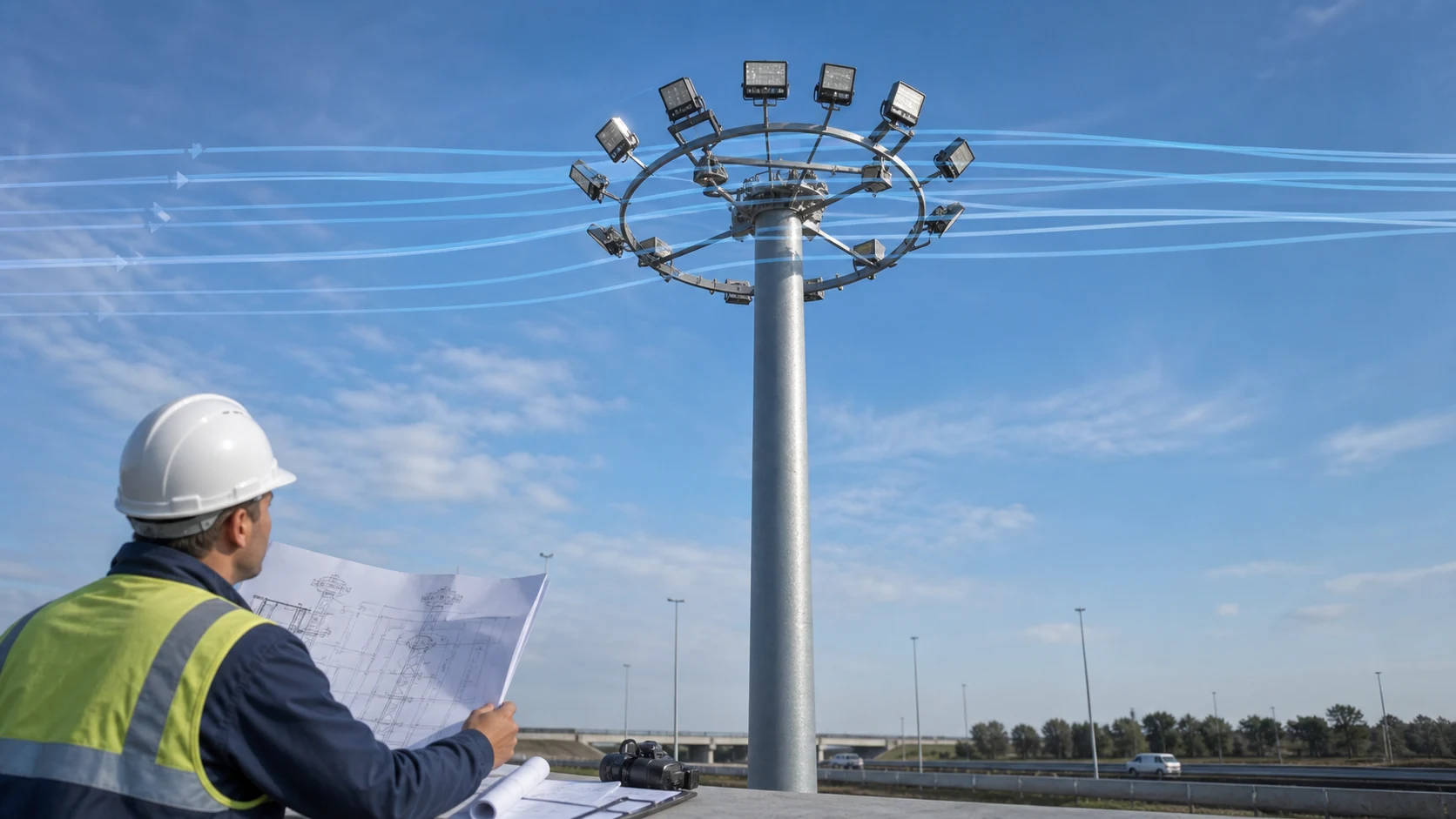
Wind load on a high mast system comes from the pole shaft, luminaires, brackets, headframe, lowering system and accessories.
The taller the structure, the more important it becomes to define the wind-loading basis clearly.
What Effective Projected Area Means
Effective projected area, often called EPA, is a structural wind-load input representing the aerodynamic effect of exposed equipment.
It should not be simplified as:
EPA = fixture length × fixture widthThe project must confirm what the supplier’s declared EPA represents.
EPA review should consider:
- Luminaire exposed area.
- Shape or drag coefficient.
- Mounting orientation.
- Luminaire tilt.
- Headframe and bracket exposure.
- Accessories.
- Pole shaft wind area.
- Multiple fixtures and possible shielding or group effects.
- Worst wind direction.
- Applicable code method.
EPA Review Table
| Item | Why It Matters | Must Confirm |
|---|---|---|
| Luminaire EPA | Affects wind load from fixtures | Supplier definition and orientation |
| Headframe EPA | Adds exposed area at mast top | Headframe drawing |
| Bracket EPA | Adds local exposed area | Bracket drawing |
| Pole shaft wind area | Often major contributor | Pole shaft drawing |
| Mounting angle | Changes exposed area and wind effect | Aiming / installation drawing |
| Accessory loads | Cameras, antennas or signs may add load | Accessory schedule |
| Worst wind direction | Controls design case | Structural calculation |
| EPA definition | Avoids supplier-to-supplier mismatch | Datasheet / calculation note |
Do not add EPA values from different suppliers blindly unless the same definition, mounting orientation and structural method are confirmed.
Headframe, Luminaire and Accessory Loads
High mast poles often support multiple luminaires on a ring, crossarm or headframe.
The structure must account for:
- Luminaire quantity.
- Individual fixture weight.
- Total fixture weight.
- Luminaire EPA.
- Headframe weight.
- Headframe EPA.
- Bracket weight.
- Bracket EPA.
- Obstruction lights.
- Cameras, antennas or sensors.
- Cable and junction box weight.
- Lowering-system components.
- Maintenance and service loads where required.
Luminaire wattage does not define structural load.
A lower-wattage LED luminaire may still have higher weight or higher EPA than another fixture. A retrofit from HID to LED may reduce electrical load while increasing or changing wind-exposed area.
For structural review, use the actual luminaire datasheet, mounting bracket drawing and headframe arrangement.
Structural Load Path and Load Combinations

A high mast structure must transfer load through a continuous path:
luminaire / headframe
→ pole shaft
→ shaft joints and welds
→ pole-to-base connection
→ base plate
→ anchor rods
→ reinforced concrete foundation
→ soil
If one interface is unclear, the entire design may be difficult to verify.
Load Types to Consider
Wind load is not the only structural input. Depending on the project and governing code, structural review may need to consider:
- Pole self-weight.
- Luminaire and headframe dead load.
- Wind load.
- Wind-induced vibration.
- Fatigue.
- Vortex shedding.
- Galloping.
- Natural wind gusts.
- Ice load where applicable.
- Seismic load where applicable.
- Maintenance and lowering loads.
- Construction and erection loads.
- Impact or accidental loads where required.
- Loads from cameras, antennas, signs or other attachments.
Static wind strength alone does not complete the structural review.
FHWA research on high-mast and other flexible roadside structures discusses the importance of wind-induced vibration, fatigue and welded connection details. That does not create a universal design rule, but it shows why high mast structures should not be treated as simple static poles only.
Pole Reaction Interface Table
| Reaction | Units | Load Combination | Coordinate Direction |
|---|---|---|---|
| Axial force | |||
| Base shear X | |||
| Base shear Y | |||
| Overturning moment X | |||
| Overturning moment Y | |||
| Torsion |
A single maximum moment value is usually not enough for foundation design unless the load combination, coordinate system, sign convention and concurrent reactions are also defined.
Required Reaction Clarifications
| Input | Required Clarification |
|---|---|
| Reaction reference point | Top of concrete, underside of base plate, pole base centerline or another defined elevation |
| Units | kN / kN·m, kip / kip-ft or other stated unit system |
| Concurrent reactions | Which axial force, shear, moment and torsion act together |
| Factoring basis | Service, allowable, factored, ultimate or project-specific basis |
| Coordinate system | X/Y directions, sign convention and relation to pole or roadway orientation |
| Load combination | Wind direction, dead load, service load, fatigue case or other governing combination |
The reference point matters. The same overturning case may produce different foundation-interface values if the moment is reported at the underside of the base plate, top of concrete or another elevation.
The foundation engineer should know whether reactions are service-level, factored, ultimate, allowable, governing wind direction, or another basis defined by the project standard.
Pole Shaft, Welds, Base Connection and Slip Joints
The pole shaft is not only a vertical tube. It is part of the structural system.
Review items may include:
- Shaft material grade.
- Shaft diameter and taper.
- Wall thickness.
- Shaft section length.
- Slip joint length.
- Longitudinal seam welds.
- Circumferential weld limitations.
- Access door reinforcement.
- Pole-to-base weld.
- Base plate flatness.
- Hot-dip galvanizing.
- Drainage and corrosion protection.
- Fabrication tolerances.
- Erection tolerances.
For high mast poles, fatigue-sensitive details may include welded connections near the base plate and access openings, depending on design and service conditions.
The project should not approve a pole only because the height and wall thickness appear reasonable. It should review the fabrication details, design basis and inspection requirements.
Anchor Bolts, Base Plate and Bolt Circle Review
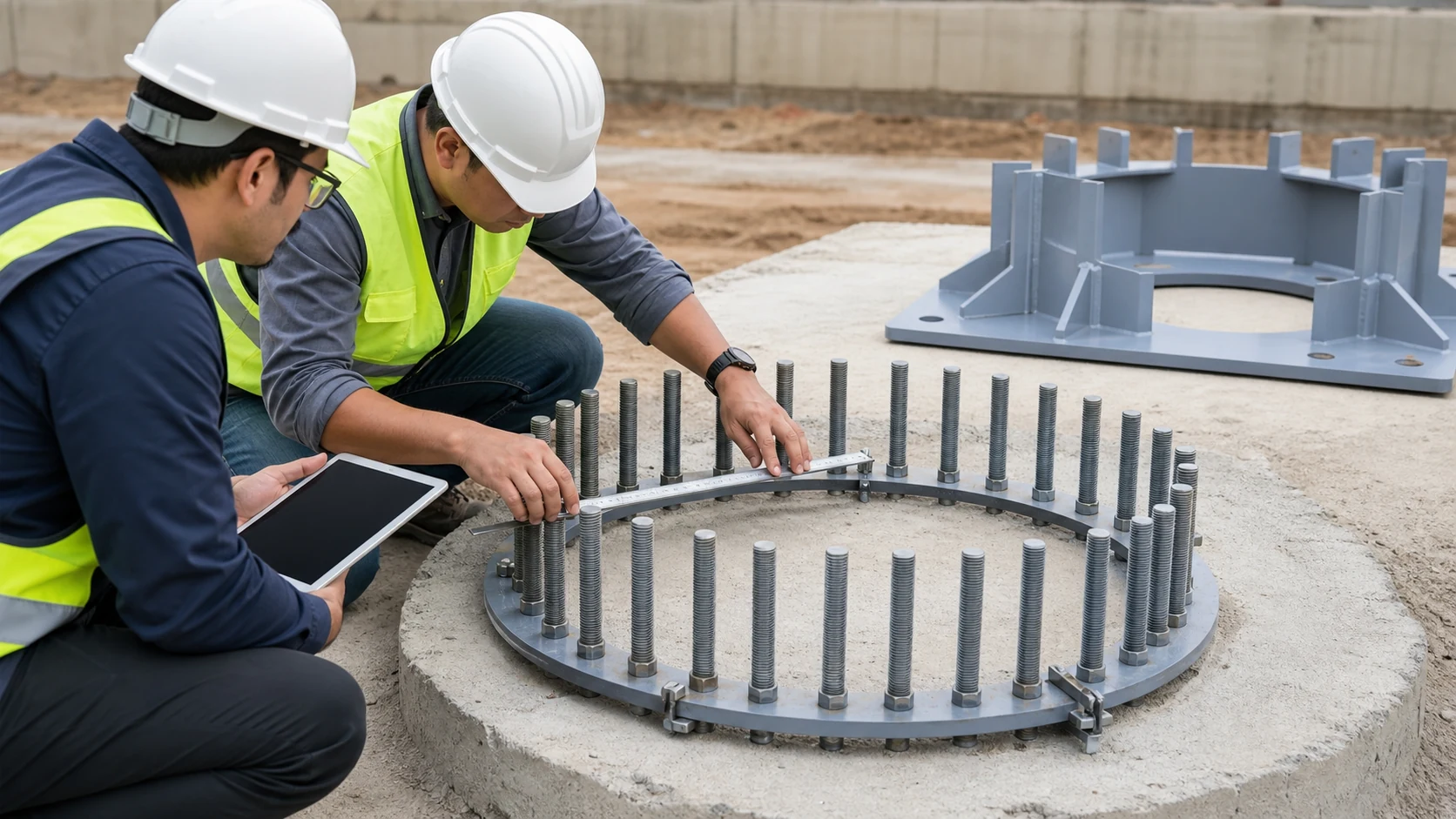
The base connection transfers pole reactions into the foundation.
It must be coordinated before anchor bolts are ordered or cast into concrete.
Check:
- Anchor bolt quantity.
- Anchor bolt diameter.
- Anchor rod material and grade.
- Thread length.
- Galvanized length.
- Bolt circle / pitch circle diameter.
- Bolt hole diameter.
- Anchor projection above concrete.
- Anchor embedment length.
- Anchor plate or anchor cage.
- Top and bottom templates.
- Nuts and washers.
- Leveling nuts.
- Grout or no-grout detail.
- Base plate diameter or dimensions.
- Base plate thickness.
- Pole-to-base weld detail.
- Conduit location.
- Reinforcement clearance.
- Installation tolerances.
- Final as-built position.
Anchor Bolt and Base Plate Interface
The anchor layout must match:
foundation reinforcement
→ anchor cage / template
→ bolt circle
→ base plate holes
→ pole orientation
→ conduit opening
→ headframe orientation
If the bolt circle is wrong, the pole may not fit the foundation. If the conduit is wrong, the electrical cable may not enter the pole correctly. If the bolt projection is wrong, leveling and nut engagement may fail.
TxDOT Item 613 is an agency-specific example showing that high mast poles include the pole and anchor bolts, and that pole and anchor-bolt requirements are controlled by project plans and specifications. This is not a universal detail, but it shows why anchor bolts should be treated as a coordinated construction interface, not as a loose procurement item.
Foundation and Soil Review
High mast foundations may include different foundation types depending on site conditions and project standards.
Possible foundation types include:
- Drilled shaft / caisson.
- Spread footing.
- Pile foundation.
- Rock anchor.
- Mat or combined foundation.
- Other project-specific foundation systems.
If an RFQ asks for a required or preferred foundation type, it should be treated as a project input that still needs structural and geotechnical confirmation.
Foundation selection may depend on:
- Soil layers.
- Allowable or ultimate bearing capacity.
- Lateral soil resistance.
- Groundwater level.
- Uplift.
- Overturning.
- Sliding.
- Settlement.
- Frost depth.
- Scour.
- Ground slope.
- Fill material or soft soil.
- Drainage.
- Corrosion environment.
- Construction access.
- Nearby utilities.
- Excavation limitations.
- Project authority requirements.
A high mast foundation should be designed or confirmed by the assigned structural and geotechnical professionals.
A supplier can often provide pole drawings, base plate details, anchor bolt layout, luminaire weight/EPA and reaction loads. The final foundation calculation may need local geotechnical data and local code compliance.
Lowering System and Maintenance Load Review
Many high mast systems include a lowering system for maintenance.
The lowering system may add:
- Ring weight.
- Cable load.
- Hoisting equipment load.
- Service load.
- Dynamic effects during operation.
- Additional mechanical components.
- Electrical and control interfaces.
- Maintenance access requirements.
The foundation and pole review should consider the complete high mast assembly, not only the pole shaft.
For retrofit projects, changing the luminaire type or quantity can change the ring load and lowering-system behavior.
Maintenance operation should be checked for:
- Safe lowering and raising.
- Balanced ring load.
- Cable condition.
- Winch or power drive condition.
- Obstruction clearance.
- Service access.
- Electrical disconnection or protection.
- Inspection interval.
Installation Tolerances and As-Built Verification

A structurally correct design can still fail at installation if anchor bolts, templates, reinforcement or conduit are misplaced.
Installation QA Table
| Item | What to Check | Why It Matters |
|---|---|---|
| Anchor template | Correct bolt circle and orientation | Prevents installation mismatch |
| Anchor bolt projection | Correct exposed length | Allows leveling, washers and nuts |
| Bolt alignment | Verticality and spacing | Prevents base plate fit-up failure |
| Concrete strength | Meets design requirement before erection | Supports safe installation |
| Reinforcement layout | No conflict with anchor cage or conduit | Prevents field rework |
| Conduit location | Matches pole base opening | Prevents cable routing problems |
| Nut tightening | Follows specified procedure | Supports connection performance |
| Grout or leveling detail | Matches design | Affects load transfer |
| Corrosion protection | Galvanizing or repair completed | Supports durability |
| As-built survey | Records actual bolt and pole position | Supports acceptance and maintenance |
| Pole verticality | Matches erection tolerance | Supports serviceability |
| Orientation | Matches lighting and headframe direction | Avoids aiming and fit-up problems |
| Foundation top elevation | Matches design and site grading | Prevents burial, fit-up or drainage problems |
| Slope away from base | Water drains away from pole base | Reduces long-term corrosion risk |
| Standing-water prevention | No ponding around base plate or anchors | Protects anchor bolts and base connection |
| Conduit sealing | Conduit entries sealed where required | Reduces water ingress and cable damage |
| Interface corrosion protection | Exposed galvanizing repairs or coating completed | Supports durability at base plate and anchors |
The as-built record is important for future maintenance, replacement and retrofit decisions.
Inspection, Fatigue and Corrosion Review
High mast poles are tall, flexible exposed structures. Their long-term performance depends on more than original design strength.
Inspection may need to review:
- Base plate corrosion.
- Anchor bolt corrosion.
- Nut and washer condition.
- Pole-to-base weld.
- Access opening reinforcement.
- Shaft corrosion.
- Galvanizing damage.
- Slip joint condition.
- Cracks at welded details.
- Foundation cracking.
- Settlement or tilt.
- Water accumulation.
- Headframe condition.
- Ring and lowering system.
- Cable and electrical components.
- Vibration or unusual movement.
FHWA inspection guidance for structural supports, although archived, discusses installation, inspection, maintenance and repair concerns for highway signs, luminaires and traffic-signal supports. It is useful background for understanding why high mast poles should be inspected as structural assets, not only as lighting equipment.
Corrosion and fatigue review is especially important in:
- Coastal areas.
- Industrial areas.
- Ports.
- Mining sites.
- High-wind regions.
- Sites with poor drainage.
- Older retrofit projects.
- Projects with incomplete original drawings.
Retrofit Projects: Can the Existing Foundation Be Reused?
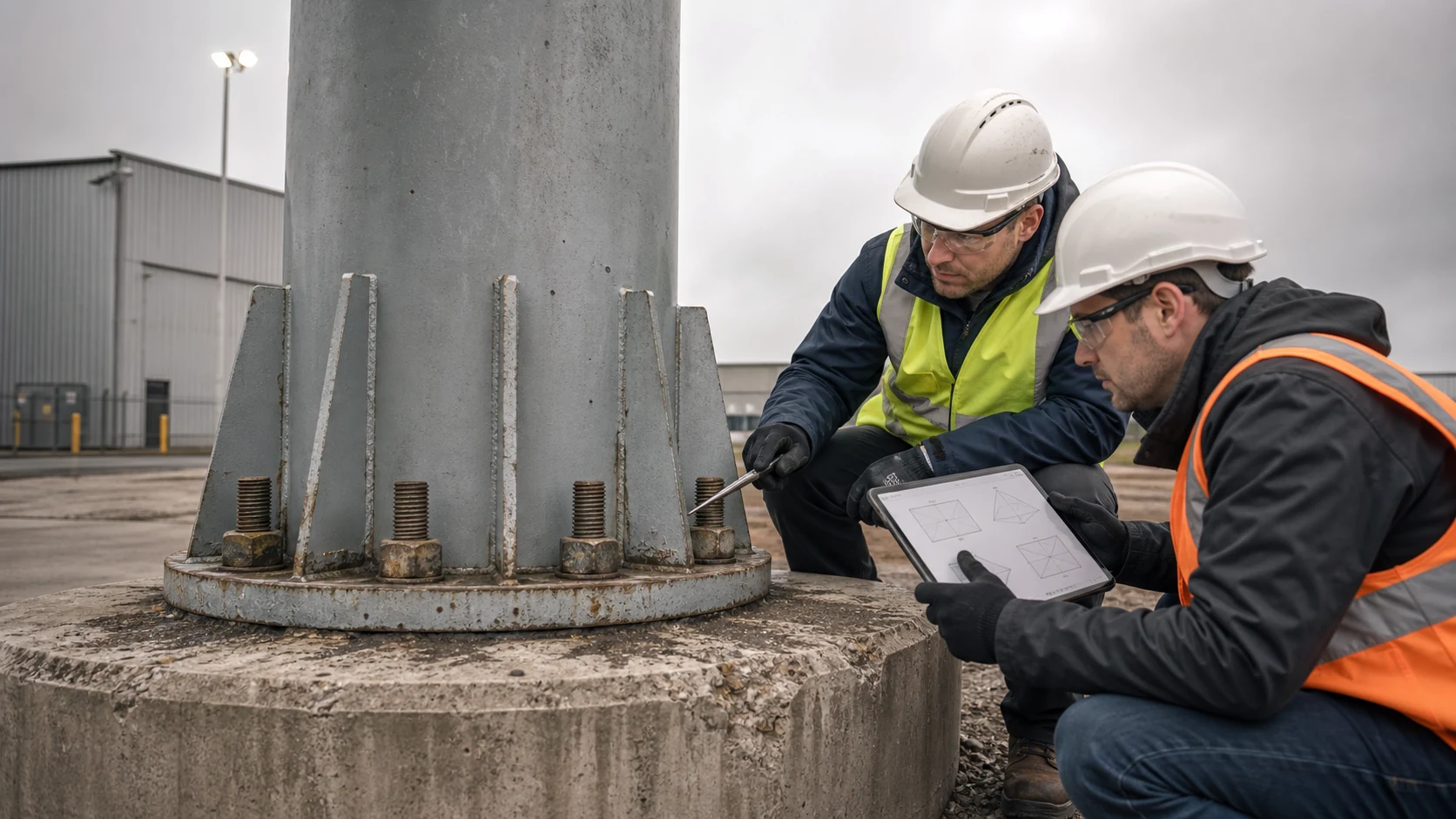
An existing foundation should not be reused by assumption.
Lower LED wattage does not automatically mean the old foundation is adequate. Structural demand may change because the new LED fixtures may have different weight, dimensions, EPA, mounting orientation or headframe arrangement.
Retrofit Foundation Review Table
| Existing Item | Retrofit Risk | Must Verify |
|---|---|---|
| Existing foundation | Unknown design basis | Original drawings or structural assessment |
| Existing anchor bolts | Corrosion, damage or insufficient capacity | Inspection and calculation |
| Existing pole shaft | Fatigue, corrosion or outdated wind criteria | Pole condition survey |
| Existing base plate weld | Fatigue-sensitive detail | Inspection and structural review |
| New LED fixtures | Different weight and EPA | Datasheet and mounting review |
| New headframe | Different load distribution | Structural compatibility |
| Lowering system | Changed ring load | Safe operation test |
| Current code requirement | May differ from original design | Local engineer / authority review |
| New accessories | Added exposed area and weight | Accessory load review |
| Site changes | Soil, drainage or surrounding exposure may change | Site reassessment |
If the original design basis cannot be confirmed, treat it as an information gap. Do not assume hidden reserve capacity.
For retrofit planning, also review the High Mast LED Retrofit Guide.
Responsibility Matrix for Pole, Foundation and Structural Review

Structural responsibility must be assigned explicitly in the contract; it should not be inferred from normal supplier practice.
Different projects may use different responsibility models:
- Supplier-designed pole with local foundation design.
- EPC-integrated structural design.
- Consultant-designed foundation.
- Manufacturer providing reaction loads only.
- Turnkey supplier responsible for full structural design.
- Authority-standard drawings with project-specific validation.
Responsibility Matrix
| Deliverable | Required Provider | Reviewer / Approver | Contract Must Clarify |
|---|---|---|---|
| Governing wind criteria | Project / authority | Structural engineer | Code, edition and wind definition |
| Pole reactions | Pole designer / supplier | Foundation engineer | Load combinations and coordinate system |
| Luminaire weight and EPA | Luminaire supplier | Pole designer | Exact model and mounting orientation |
| Pole calculation | Assigned structural designer | Consultant / authority | Professional seal if required |
| Foundation calculation | Assigned foundation designer | Consultant / authority | Geotechnical basis |
| Anchor layout | Pole / foundation interface owner | Both designers | Bolt circle, projection and tolerances |
| Shop drawings | Fabricator / supplier | Project reviewer | Submission and approval process |
| Installation method | Contractor / EPC | Site engineer / authority | Tolerances, QA and safety procedure |
| As-built records | Contractor / EPC | Owner / consultant | Measurement and acceptance format |
The contract should define which party supplies, checks and approves each structural document.
Tender / RFQ Checklist for Structural Inputs
A good RFQ should not ask only for “30m high mast pole price.”
It should define the structural input package required for review.
Tender / RFQ Checklist
| RFQ Item | Why It Matters |
|---|---|
| Project location | Defines wind, corrosion and local code context |
| Governing code and edition | Defines design basis |
| Wind-speed definition | Prevents incorrect comparison |
| Design wind speed | Required for pole and foundation review |
| Exposure / terrain category | Affects wind pressure |
| Geotechnical report | Required for foundation design |
| Pole height | Main geometry input |
| Pole shaft drawing | Required for structural review |
| Luminaire quantity | Affects headframe load |
| Luminaire weight | Affects dead load |
| Luminaire EPA | Affects wind load |
| Headframe drawing | Defines load distribution |
| Lowering system details | Defines service and mechanical load |
| Base plate drawing | Defines connection interface |
| Anchor bolt drawing | Required for civil works |
| Reaction loads | Required for foundation engineer |
| Load combinations | Needed to interpret reactions |
| Corrosion protection | Supports durability |
| Installation tolerance | Prevents construction mismatch |
| Shop drawing requirement | Defines approval process |
| Professional seal requirement | Defines responsibility and jurisdiction |
Copyable RFQ Template
Project location:
Application:
Pole height:
Number of masts:
Luminaire quantity per mast:
Luminaire model:
Luminaire weight:
Luminaire EPA:
Headframe type:
Lowering system:
Accessories:
Governing code and edition:
Wind-speed definition:
Design wind speed:
Exposure / terrain category:
Risk category / return period:
Special wind / seismic / ice condition:
Geotechnical report available:
Required, preferred or anticipated foundation type, if already defined:
Required deliverables:
Required reaction format:
Anchor bolt drawing required:
Base plate drawing required:
Professional seal required:
Tender / authority review process:
Common Foundation and Wind Load Mistakes
| Mistake | Why It Creates Risk | Better Review Method |
|---|---|---|
| Selecting foundation size from pole height only | Ignores wind, soil, EPA and code | Use project-specific structural calculation |
| Using a fixed 30m foundation table | May not match site conditions | Confirm wind and geotechnical inputs |
| Comparing wind speed without definition | Different standards use different bases | State code, edition, exposure and wind definition |
| Treating EPA as length × width | Ignores aerodynamic definition | Confirm supplier EPA definition and orientation |
| Ignoring luminaire and headframe loads | Understates top load | Use actual datasheets and drawings |
| Ignoring pole reactions | Foundation engineer lacks design input | Provide axial, shear, moment and torsion |
| Ordering anchor bolts before final drawings | Bolt circle may not match base plate | Coordinate template, base plate and foundation |
| Ignoring conduit and rebar conflicts | Causes field rework | Check anchor cage and civil details |
| Assuming lower LED wattage reduces structural demand | Weight and EPA may not reduce | Compare actual fixture data |
| Reusing old foundations without review | Original basis may be unknown | Inspect, measure and recalculate |
| Checking only static wind strength | Fatigue and vibration may matter | Review applicable fatigue and inspection requirements |
| Leaving responsibility unclear | Creates approval and liability gaps | Define provider, reviewer and approver in contract |
Request a High Mast Structural Input Review
High mast foundation, wind load, anchor bolts and base plate details should be reviewed before civil construction and anchor bolt procurement.
Send us your project location, pole height, luminaire quantity, luminaire weight and EPA, headframe type, design wind criteria, geotechnical information and required tender deliverables. Sunlurio can support pole drawings, luminaire data, anchor-bolt coordination inputs, IES/LDT files, DIALux coordination and BOQ documentation for high mast lighting projects.
Request a High Mast Structural Input Review
Related High Mast Lighting Guides
The following guides explain related high mast project decisions:
- High Mast Pole Height Guide
- High Mast Light Wattage Guide
- High Mast LED Retrofit Guide
- High Mast Lighting Level Specification Guide
- High Mast Pole Spacing Guide
- High Mast Lighting Layout Patterns
- How Many High Mast Lights Do You Need?
- High Mast Lighting Coverage Explained
- High Mast Lighting Systems
- Engineering Support for Lighting Projects
- Drawings and Datasheets
- Tender Documents and BOQ Support
Frequently Asked Questions
What is the standard foundation size for a 30m high mast pole?
There is no universal standard foundation size for a 30m high mast pole. Foundation size depends on wind criteria, soil conditions, pole reactions, luminaire weight, EPA, headframe, foundation type and local structural code.
Can foundation depth be estimated as pole height divided by six?
That rule may appear in informal discussions, but it should not be used for final design. It does not define wind speed, soil condition, load combinations, EPA, code requirements or safety factors.
What information is needed before foundation design?
At minimum, the project should define pole height, wind criteria, soil and geotechnical data, luminaire quantity, fixture weight, EPA, headframe type, pole reactions, base plate drawing and anchor bolt layout.
What is EPA in high mast pole design?
EPA means effective projected area. It is a wind-load input representing the aerodynamic effect of exposed equipment. The project must confirm the supplier’s EPA definition, mounting orientation and whether drag effects are included.
Does luminaire wattage affect wind load?
Wattage does not directly define structural load. Structural review uses fixture weight, dimensions, EPA, mounting orientation and quantity. A lower-wattage LED fixture may still have significant weight or exposed area.
Who designs the high mast foundation?
This depends on the contract. The supplier may provide pole drawings, base details, reaction loads and luminaire data. The final foundation design is often confirmed by a local structural or geotechnical engineer using project-specific soil and code requirements.
What are pole reactions?
Pole reactions are the forces and moments transferred from the pole to the foundation. They may include axial force, base shear, overturning moment and torsion under defined load combinations.
Can an existing foundation be reused in a retrofit project?
Possibly, but it must be verified. The project should check original drawings, design wind basis, anchor bolts, pole condition, corrosion, fatigue, new fixture weight, new EPA and current code requirements.
Why are anchor bolt templates important?
Anchor bolt templates keep the bolts in the correct position and orientation during concrete placement. A wrong bolt circle or projection can prevent the base plate from fitting during installation.
Should fatigue be reviewed for high mast poles?
Fatigue may be relevant for tall, flexible high mast structures, especially in windy locations or where welded details and dynamic wind effects are critical. The applicable structural standard and project engineer should determine the fatigue review requirement.
Can Sunlurio provide foundation calculations?
Sunlurio can support high mast project inputs such as pole drawings, luminaire weight and EPA, anchor layout coordination, datasheets and project documentation. Final foundation calculation responsibility should be defined by the contract and confirmed by qualified structural and geotechnical professionals according to local requirements.
Engineering References
The following references are engineering background sources. They do not create a universal foundation size or anchor-bolt design for all high mast projects.
- FHWA Fatigue Testing of Galvanized and Ungalvanized Socket Connections — background on wind-induced vibration, fatigue and welded socket connection behavior for highmast light poles and related structures.
- FHWA Ancillary Structures Inspection Reference Manual — background for inspection of ancillary highway structures, including high mast lighting.
- TxDOT Item 613: High Mast Illumination Poles — agency-specific example showing that high mast poles include the pole and anchor bolts.
- TxDOT Highway Illumination Manual: High Mast Lighting Assemblies — agency-specific context showing that Item 613 covers poles and anchor bolts, Item 416 covers foundations, standard pole heights and wind speeds are part of the TxDOT system, and HMIF sheets provide TxDOT foundation details.
- FHWA Guidelines for the Installation, Inspection, Maintenance and Repair of Structural Supports for Highway Signs, Luminaires, and Traffic Signals — archived background guidance for structural support inspection and maintenance.
- AASHTO structural-support standards, ASCE 7, ACI 318, AISC, AWS D1.1, ASTM F1554 and local codes where adopted by the project — use only when the project specifically defines the applicable standard, edition and jurisdiction.