

Quick Answer
A high mast lighting lowering system allows the luminaire ring or carrier to be lowered to ground level for inspection and service. It typically includes a headframe, luminaire ring, winch or drive unit, hoist wire ropes, sheaves, latch or locking devices, power cable, connectors, controls, limit devices and grounding or bonding provisions.
The lowering system should be reviewed as a safety-critical mechanical maintenance subsystem, not as a minor pole accessory.
For EPC, municipal, port, airport, highway and industrial projects, the correct review should confirm the rated load, ring configuration, luminaire quantity, fixture weight, wire rope system, latch arrangement, control method, structural coordination, FAT evidence, site commissioning record and O&M handover documents.
This article is a buyer, EPC and project-review guide. It is not a public repair manual. Abnormal lowering-system behavior should be treated as a stop-and-escalate condition, not as a trial-and-error repair task.
Project Review Summary
| Item | Project Review Point |
|---|---|
| Main Topic | High mast lighting lowering system review |
| Main Question | How should a high mast lowering device be specified, inspected, tested and handed over? |
| Best-Fit Projects | EPC, municipal, highway, port, airport, logistics, industrial, mining and retrofit high mast projects |
| Main Risk | Treating the lowering system as a simple accessory instead of a safety-critical mechanical subsystem |
| Main Components | Winch, wire rope, sheaves, luminaire ring, latch, headframe, control box, power cable, limit devices and grounding |
| Required Review | Rated capacity, ring load, latch function, wire rope condition, control safety, structural coordination and commissioning evidence |
| Typical Deliverables | Drawings, component datasheets, rated-load evidence, FAT/SAT records, commissioning report, O&M manual, tools and spare-parts list |
| Project Benefit | Reduces maintenance risk, commissioning disputes, retrofit uncertainty and incomplete tender submittals |
What Is a High Mast Lighting Lowering System?
A high mast lighting lowering system is a mechanical and electrical subassembly that allows the luminaire ring or carrier to move between the operating position near the top of the mast and a service position near ground level.
Its purpose is to reduce routine work at height during luminaire inspection, cleaning, wiring checks, driver replacement or other approved maintenance activities.
A typical lowering system may include:
- Headframe or top assembly.
- Pulley or sheave arrangement.
- Hoist wire ropes.
- Luminaire ring or carrier.
- Latch or locking system.
- Winch or drive unit.
- Portable motor drive or integrated motor.
- Power cable and connector.
- Control box.
- Limit or over-travel protection.
- Grounding and bonding provisions.
- Operation tools and O&M manual.
A functioning lowering system can reduce routine work at height. It does not eliminate every need for specialist access equipment. If the lowering system itself fails, if the headframe or latch requires high-level inspection, or if structural work is required, professional access equipment may still be needed.
Why the Lowering System Is Safety-Critical
The lowering system moves a heavy luminaire ring and multiple luminaires. It also interfaces with electrical power, structural load paths and maintenance personnel.
Therefore, it should be treated as a safety-critical subsystem.
Important risks include:
- Uncontrolled ring movement.
- Wire rope wear or damage.
- Sheave misalignment.
- Latch failure or incomplete engagement.
- Ring imbalance.
- Electrical cable damage.
- Control malfunction.
- Over-travel.
- Incorrect operation.
- Inadequate exclusion zone.
- Missing O&M documentation.
- Unknown retrofit load changes.
The public article should not teach users how to release a stuck latch, reverse-jog a motor, adjust wire rope length, rewrap a drum or bypass a safety device. Those actions require the exact OEM procedure, project method statement and qualified personnel.
The correct public guidance is:
Stop operation.
Isolate the area.
Keep personnel away from suspended loads.
Preserve the condition for inspection.
Refer to the OEM manual and project method statement.
Escalate to qualified personnel.
Main Subassemblies of a High Mast Lowering System
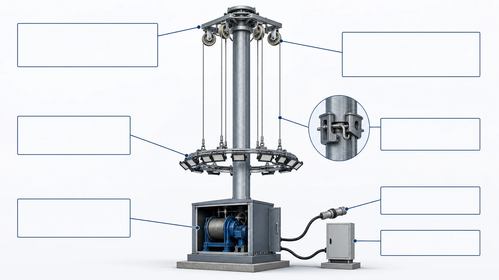
A high mast lowering system should be reviewed as a complete assembly, not as separate parts purchased independently.
Headframe and Sheave Arrangement
The headframe supports the upper mechanical arrangement. It may include sheaves, guiding components, latch interfaces and structural brackets.
Review:
- Headframe material and coating.
- Load rating.
- Sheave location and alignment.
- Latch interface.
- Wire rope routing.
- Electrical cable routing.
- Inspection access.
- Compatibility with pole top and luminaire ring.
- Structural and wind-load coordination.
Luminaire Ring or Carrier
The luminaire ring carries the luminaires, brackets, junction components and sometimes accessories.
Review:
- Rated luminaire quantity.
- Total ring mass.
- Fixture mass.
- Fixture mounting method.
- Balance and load distribution.
- Bracket design.
- Connector arrangement.
- EPA and wind-load input.
- Grounding and bonding.
- Latch compatibility.
- Maintenance access at ground level.
Winch and Drive System
The winch or drive controls raising and lowering.
It may be manual, operated by a portable motor drive, or integrated with a fixed motor. The selection should be based on rated load, project maintenance strategy, operator procedure, power availability and OEM evidence.
Hoist Wire Ropes
Hoist wire ropes support movement of the luminaire ring. Their diameter, construction, material, terminations and safety factor should be defined by the system design, manufacturer data, project specification and applicable standards.
Do not assume a universal wire rope size for all high mast systems.
Latching or Locking System
The latch or locking system helps hold or transfer load when the luminaire ring is in its operating position, depending on the system design.
Not all systems use the same latch location or mechanism. Some systems may use top-latching, bottom-latching or manufacturer-specific arrangements.
Review should follow the exact system design.
Electrical Power Cable and Connector
The lowering system may include power cables and connectors that move or disconnect during service.
Review:
- Cable rating.
- Strain relief.
- Connector type.
- Cable routing.
- Protection from rubbing or twisting.
- Grounding and bonding.
- Compatibility with LED drivers and controls.
- Safe isolation procedure.
Control and Limit Devices
Control components may include buttons, control boxes, portable-drive interfaces, limit switches, overload protection, emergency stops or other protection depending on the product.
Do not assume all systems have the same functions. Require bidder evidence and project-specific commissioning records.
Lowering System Component Review Matrix
| Component | Design Input | Bidder Evidence | Inspection Point | Acceptance Record |
|---|---|---|---|---|
| Headframe | Load path, sheave arrangement, latch interface | Drawing, BOM, material/coating data | Alignment, coating, mounting, deformation | Shop inspection / site record |
| Luminaire ring | Total load, fixture quantity, balance | Ring drawing, fixture schedule, weight data | Mounting, balance, connector position | FAT / site commissioning |
| Winch / drive | Rated load, operation method | Rated-capacity data, manual, test record | Smooth movement, brake/control function | FAT / SAT record |
| Wire rope | Diameter, material, construction, termination | Manufacturer data, certificate if required | Wear, corrosion, routing, tension condition | Inspection record |
| Sheave / pulley | Diameter, groove, alignment, bearing | Drawing, component specification | Rotation, wear, cable contact | Inspection record |
| Latch / lock | Load-transfer method, engagement status | Drawing, OEM procedure, test method | Engagement, release, indication | Commissioning witness record |
| Power cable | Cable type, rating, routing | Cable datasheet, wiring diagram | Rubbing, strain relief, connector condition | Electrical inspection |
| Control box | Operation mode and protection functions | Wiring diagram, control description | Buttons, E-stop, limit functions | Functional test record |
| Grounding / bonding | Project electrical safety requirement | Grounding diagram, test requirement | Continuity and connection condition | Electrical test record |
| Tools / spares | Operation and maintenance support | Tool list, spare-parts list | Availability and custody | Handover record |
Manual Winch, Portable Motor Drive or Integrated Motor?
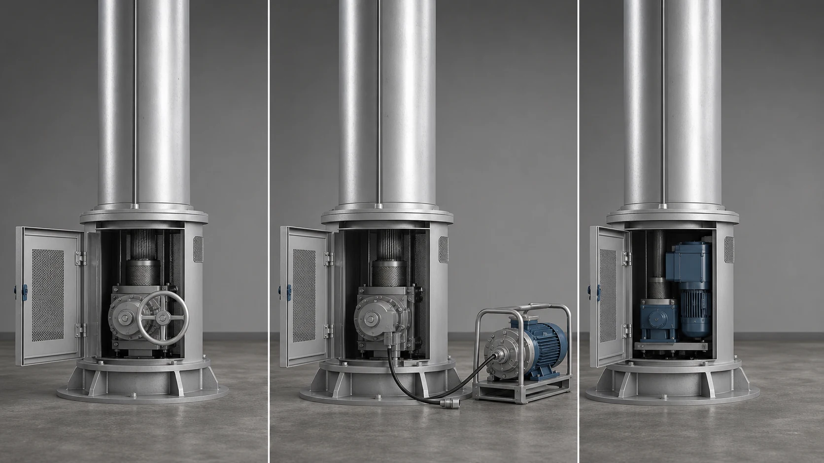
High mast lowering systems should not be compared only as “manual vs motorized.” Many projects also use a portable motor drive that can be connected to different masts.
Selection depends on project requirements, not a universal height rule.
| Review Item | Manual Winch | Portable Motor Drive | Integrated Motor |
|---|---|---|---|
| Drive arrangement | Hand-operated | Shared powered drive tool | Fixed motor at each mast or system-specific arrangement |
| Typical project context | Smaller systems or low-frequency service | Multiple masts needing controlled powered operation | Maintenance-sensitive or larger systems where fixed power operation is justified |
| Rated-load evidence | Required | Required | Required |
| Power requirement | No dedicated motor power | Portable power source or project-defined supply | Permanent or system-defined power supply |
| Operator and tool arrangement | Defined by OEM and project method statement | Tool custody and interface must be controlled | Control box and protection functions must be verified |
| Speed and control | Per manufacturer data only | Per manufacturer data only | Per manufacturer data only |
| Brake / overload / limit functions | Confirm system-specific functions | Confirm drive and interface functions | Confirm motor, brake, control and limit functions |
| Maintenance complexity | Usually lower mechanically | Tool and interface require management | Motor and controls require more maintenance review |
| Storage / security | Winch remains part of mast system | Portable drive storage and custody required | Motor and control equipment exposed to site environment |
| Initial and lifecycle cost | Lower initial cost may be possible | Shared tool may reduce per-mast equipment cost | Higher equipment cost may be justified by maintenance strategy |
| Required handover items | Manual, tools, inspection checklist | Drive tool, interface data, custody procedure | Electrical/control manual, spare parts, test records |
Do not specify fixed operating speed, personnel count, gear ratio or height range unless it comes from the selected manufacturer and project specification.
Luminaire Ring and Headframe Review
The luminaire ring and headframe determine how the fixtures are supported and moved.
Review questions include:
- How many luminaires are mounted?
- What is the total fixture mass?
- Are brackets and accessories included in the ring load?
- Is the ring balanced?
- Does the ring self-center or use a guide system?
- How does the latch engage?
- How is electrical connection made?
- Are the power cable and connectors protected during travel?
- Is the ring suitable for the selected luminaire model?
- Has LED retrofit changed the mass, EPA or center of gravity?
- Is the parked or latched condition coordinated with structural design?
The ring should not be evaluated only by luminaire wattage. Use actual luminaire mass, bracket mass, quantity, mounting position, EPA and cable arrangement.
For structural coordination, review the High Mast Pole Foundation & Wind Load Guide.
Wire Rope, Sheave and Winch Review

Wire rope, sheaves and winch components should be reviewed through evidence, inspection and approved procedure.
A public project guide should not publish universal rope diameter, universal safety factor, universal discard criteria or field adjustment instructions. Different official specifications and manufacturers may use different rope sizes, materials and arrangements.
Review evidence should include:
- Wire rope specification.
- Material and corrosion protection.
- Construction type if defined.
- Termination method.
- Sheave size and groove profile.
- Winch rated capacity.
- Brake or holding function.
- Cable routing.
- Drum winding arrangement.
- Inspection method.
- Replacement criteria defined by OEM or project standard.
- Maintenance record.
Stop-and-escalate warning signs include:
- Broken strands.
- Kinking.
- Severe corrosion.
- Birdcaging.
- Flattening.
- Unusual noise.
- Slack rope.
- Rope rubbing.
- Sheave seizure.
- Drum winding disorder.
- Ring tilt.
- Ring jamming.
- Uncontrolled movement.
The article should not instruct unqualified personnel to adjust cable length, rewrap the drum, release a latch or continue operation to “test again.”
Latching and Load-Transfer Review
The latch or locking system is one of the most important safety-related parts of the lowering system.
When the luminaire ring is in service position, the system should hold or transfer the load according to the original design. The winch, wire ropes, latch, headframe and ring must function together.
Review:
- Latch type and location.
- Engagement method.
- Release method.
- Confirmation or indication method.
- Load-transfer path.
- Synchronization between multiple latch points if applicable.
- Inspection access.
- Functional test method.
- OEM acceptance criteria.
- Handover procedure.
- Warning signs for incomplete engagement.
Do not assume all systems are top-latching or bottom-latching. The project must use the actual manufacturer’s design.
If latch status is unclear, the system should not be treated as normally commissioned or ready for routine service.
Electrical, Control and Grounding Review
Lowering systems can include moving or disconnectable electrical components. These must be reviewed together with mechanical operation.
Check:
- Control box location.
- Operation mode.
- Emergency stop.
- Limit or over-travel protection.
- Portable drive interface.
- Power supply.
- Isolation procedure.
- Connector rating.
- Cable strain relief.
- Cable routing during ring travel.
- Grounding and bonding.
- Lightning protection coordination.
- Terminal block condition.
- LED driver compatibility.
- Dimming or control wiring if applicable.
Electrical modifications and testing should be carried out by qualified personnel according to project requirements, OEM procedures, local electrical codes and lockout/tagout requirements where applicable.
Structural and Wind-Load Coordination
The lowering system affects the structural review of the high mast assembly.
The structural team may need:
- Total luminaire ring mass.
- Fixture mass.
- Bracket mass.
- Accessory mass.
- Ring center of gravity.
- Headframe geometry.
- Latch load-transfer arrangement.
- Pole-top interface.
- Dynamic or maintenance load condition.
- Parked / latched condition.
- Luminaire EPA.
- Headframe EPA.
- Cable and accessory loads.
- Retrofit configuration changes.
The foundation and pole review should not ignore the lowering system. For wind-load and foundation inputs, see the High Mast Pole Foundation & Wind Load Guide.
New Build Tender Evidence Matrix
A tender should define not only the required product features, but also the evidence required before acceptance.
| Requirement | Bidder Submittal | FAT Evidence | Site Test | Handover Record |
|---|---|---|---|---|
| Lowering system scope | System drawing, BOM, component list | Assembly inspection | Installed-system inspection | Approved as-built package |
| Rated capacity | Rated-load statement and design basis | Load-related test or certificate if required | Functional demonstration under project procedure | Rated-capacity record |
| Ring configuration | Ring drawing, luminaire layout, weight data | Ring assembly inspection | Ring travel and balance check | Ring configuration record |
| Winch / drive | Datasheet, manual, capacity evidence | Functional test | Raising/lowering demonstration | Operation manual and tool list |
| Wire rope | Specification and termination detail | Material/inspection record if required | Routing and condition check | Inspection and replacement guidance |
| Latch / lock | Design description and drawing | Engagement/release test if required | Engagement confirmation | OEM procedure and inspection record |
| Control system | Wiring diagram, control description | Control test | E-stop/limit/control function test | Electrical record |
| Grounding / bonding | Grounding diagram | Continuity evidence if required | Site electrical test | Test record |
| Spares and tools | Spare-parts list and tool list | Packing / custody check | Tool compatibility check | Handover list |
| O&M documents | Manuals and safety procedure | Document review | Training / demonstration record | Final O&M file |
This table is a review framework. The exact FAT and SAT requirements should follow the project specification, OEM procedure and authority requirements.
FAT, Installation and Commissioning Checks

Commissioning should prove that the installed lowering system matches the approved configuration and operates under the accepted procedure.
Do not reduce commissioning to “raise and lower once.”
Commissioning Record Matrix
| Test Item | Procedure Reference | Inspector / Witness | Evidence | Acceptance Criteria | NCR / Action |
|---|---|---|---|---|---|
| Installed configuration | Approved drawing / BOM | Photo / checklist | Matches approved system | ||
| Ring assembly | Ring drawing | Inspection record | Correct fixture quantity and mounting | ||
| Wire rope routing | OEM procedure | Photo / inspection note | No rubbing, twisting or abnormal routing | ||
| Raising operation | OEM / project method | Witness record | Smooth movement within accepted procedure | ||
| Lowering operation | OEM / project method | Witness record | Controlled movement within accepted procedure | ||
| Ring balance | OEM criteria | Photo / measurement if required | Meets OEM/project criteria | ||
| Latch engagement | OEM procedure | Witness record | Confirmed engagement / indication | ||
| Control box | Wiring diagram / control manual | Functional test | Buttons and controls operate correctly | ||
| Limit / over-travel | OEM procedure | Test record | Stops according to design | ||
| Emergency stop | Control procedure | Test record | Functions as required | ||
| Grounding / bonding | Electrical test requirement | Test result | Meets project requirement | ||
| Handover documents | Contract requirement | Document list | Manual, tools, spares and records delivered |
If defects are found, they should be recorded as NCRs or punch-list items and closed before handover.
Maintenance Access and Ground-Level Service Review
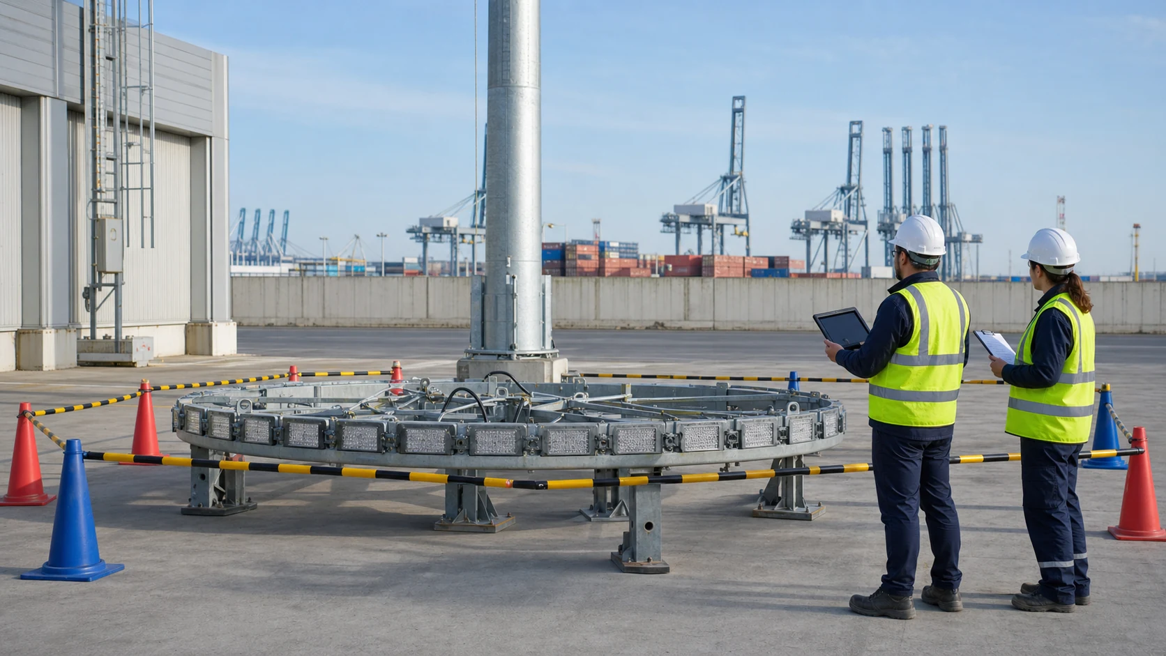
Ground-level service is one of the main benefits of a lowering system, but it must be planned.
Review:
- Safe service area around the mast.
- Exclusion zone.
- Vehicle access.
- Lighting ring service height.
- Weather limitations.
- Electrical isolation.
- Tool custody.
- Spare-part availability.
- Qualified personnel requirement.
- OEM manual availability.
- Site maintenance record format.
- Rescue or emergency planning if applicable.
A lowering system can reduce routine luminaire servicing at height. It does not make maintenance risk-free.
For maintenance planning, inspection schedules and O&M records, review the High Mast Light Maintenance Guide.
Common Warning Signs and Safe Response
This section is for risk recognition, not repair instruction.
| Warning Sign | Possible Subsystem Category | Immediate Safe Response | Required Follow-Up |
|---|---|---|---|
| Ring does not lower | Latch, winch, control, load path or cable issue | Stop operation and isolate area | Qualified diagnosis using OEM procedure |
| Ring tilts during movement | Load balance, rope, guide or termination issue | Stop movement if unsafe | Inspection and engineering review |
| Abnormal noise | Winch, sheave, cable or guide issue | Stop and record condition | Mechanical inspection |
| Wire rope appears damaged | Rope wear, corrosion or fatigue | Stop use | OEM/standard-based discard and replacement review |
| Rope becomes slack or disordered | Winch drum, routing or load issue | Stop operation | Qualified inspection |
| Latch status unclear | Locking or indication issue | Do not treat system as ready for service | Functional test and approval |
| Cable rubs or twists | Routing or strain-relief issue | Stop if damage risk exists | Electrical/mechanical review |
| Control does not respond normally | Control box, power supply or limit issue | Stop and isolate | Electrical review |
| Ring jams | Guide, latch, pole alignment, rope or sheave issue | Do not force operation | Specialist inspection |
| Uncontrolled movement | Serious mechanical or control hazard | Clear area and escalate immediately | Emergency procedure and investigation |
Do not continue operating a lowering system to “see if it clears itself.”
Retrofit Projects: Can the Existing Lowering System Be Reused?
An existing lowering system should not be reused by assumption.
A LED retrofit may change:
- Fixture mass.
- Fixture quantity.
- Bracket design.
- Ring balance.
- EPA.
- Center of gravity.
- Electrical connector arrangement.
- Power cable requirements.
- Driver and control wiring.
- Maintenance procedure.
Lower LED wattage does not prove that the lowering system is suitable.
Retrofit Reuse Decision Table
| Existing Item | Retrofit Risk | Must Verify | Approval Decision |
|---|---|---|---|
| Nameplate / model | Unknown system identity | Manufacturer, model, rated capacity | Accept / reject / investigate |
| Original drawing / manual | Missing design basis | Drawings, O&M manual, parts list | Accept / reject / investigate |
| Rated capacity | New load may exceed original basis | Existing rating vs new ring load | Accept / reject / replace |
| Winch / drive | Wear or incompatible capacity | Inspection and functional test | Accept / repair / replace |
| Wire rope | Corrosion, broken strands or fatigue | Inspection and OEM criteria | Accept / replace |
| Sheave / pulley | Wear or misalignment | Rotation and groove condition | Accept / repair / replace |
| Luminaire ring | New fixture weight may differ | Ring mass, balance and mounting | Accept / modify / replace |
| Latch / lock | Failure to engage or release | Functional test and indication check | Accept / repair / replace |
| Power cable / connector | New LED system may need different wiring | Electrical and mechanical compatibility | Accept / modify / replace |
| Control box | Incompatible with new drive/control strategy | Electrical review | Accept / modify / replace |
| EPA and wind input | New fixtures may change wind demand | Structural/wind-load review | Accept / redesign |
| Maintenance history | Unknown service record | Inspection history and failure record | Accept / investigate |
If traceability is incomplete, treat it as an information gap, not as approval.
For LED retrofit planning, also review the High Mast LED Retrofit Guide.
Tender / RFQ Checklist for Lowering Systems
A complete lowering-system RFQ should request both product information and acceptance evidence.
Buyer Input Checklist
| Buyer Input | Why It Matters |
|---|---|
| Project location | Defines environment, corrosion, wind and authority requirements |
| Mast height | Affects system arrangement and maintenance strategy |
| Number of masts | Affects tool strategy and maintenance planning |
| New build or retrofit | Defines available drawings and reuse risk |
| Luminaire quantity per mast | Determines ring load |
| Luminaire model and weight | Required for load and balance review |
| Luminaire dimensions and EPA | Required for wind and structural coordination |
| Headframe type | Defines system compatibility |
| Preferred drive arrangement | Manual, portable drive or integrated motor if already specified |
| Power availability | Affects motor or portable-drive strategy |
| Existing system manufacturer/model | Required for retrofit traceability |
| Existing drawings/manuals/photos | Supports reuse decision |
| Known faults or history | Identifies risk before quotation |
| Required FAT/SAT | Defines acceptance evidence |
| Required O&M handover | Defines manuals, tools, spares and training |
| Tender deadline | Supports document planning |
Supplier Submittal Checklist
| Supplier Submittal | Purpose |
|---|---|
| Lowering system drawing | Shows arrangement and interfaces |
| Component BOM | Defines scope |
| Rated capacity evidence | Confirms load basis |
| Ring drawing | Confirms fixture layout and balance |
| Wire rope specification | Confirms rope and termination basis |
| Winch / drive datasheet | Confirms drive arrangement |
| Latch / lock description | Confirms load-transfer mechanism |
| Control wiring diagram | Confirms control and protection functions |
| Grounding / bonding details | Supports electrical safety review |
| Installation method statement | Supports site planning |
| Commissioning procedure | Defines acceptance test |
| O&M manual | Supports future maintenance |
| Tools and spare-parts list | Supports handover and service readiness |
| Warranty and service conditions | Defines support boundary |
Request a High Mast Lowering System Review
High mast lowering systems should be reviewed before procurement, installation, commissioning and retrofit reuse decisions.
Send us your project location, mast height, number of masts, luminaire configuration, luminaire weight, existing system photos, drawings, manuals, known faults, tender requirements and handover expectations. Sunlurio can support high mast lowering-system review, luminaire configuration coordination, structural input coordination, tender documentation, BOQ support and commissioning evidence preparation.
Request a High Mast Lowering System Review
Related High Mast Lighting Guides
The following guides explain related high mast project decisions:
- High Mast Pole Foundation & Wind Load Guide
- High Mast LED Retrofit Guide
- High Mast Light Maintenance Guide
- High Mast Pole Height Guide
- High Mast Light Wattage Guide
- High Mast Lighting Level Specification Guide
- High Mast Pole Spacing Guide
- High Mast Lighting Layout Patterns
- High Mast Lighting Systems
- Engineering Support for Lighting Projects
- Tender Documents and BOQ Support
Frequently Asked Questions
What is a high mast lighting lowering system?
A high mast lighting lowering system is a mechanical and electrical system that allows the luminaire ring or carrier to be lowered to ground level for inspection and service. It typically includes a headframe, winch or drive, wire ropes, sheaves, ring, latch, controls and electrical connections.
Does a lowering system eliminate the need for a crane or bucket truck?
No. A functioning lowering system can reduce routine luminaire servicing at height, but specialist access equipment may still be required for lowering-system failure, headframe inspection, structural work, pole repair or system replacement.
What is the difference between manual, portable-drive and integrated motor systems?
A manual system is hand-operated. A portable-drive system uses a shared powered drive tool. An integrated motor system includes a fixed motor or system-specific powered arrangement. The right choice depends on rated load, project scale, maintenance frequency, power availability, operator procedure and OEM evidence.
What supports the luminaire ring when it is in service?
That depends on the system design. The load may be transferred through latch or locking components, wire rope, headframe and other system-specific mechanisms. The project should confirm the actual load-transfer path from the manufacturer’s drawings and commissioning evidence.
What should be checked on high mast wire ropes and sheaves?
Check manufacturer data, routing, corrosion, broken strands, kinking, rubbing, sheave rotation, alignment, terminations and maintenance records. Exact discard criteria should follow the OEM manual, project specification and applicable standards.
Why can a luminaire ring tilt or jam?
Possible causes include ring imbalance, wire rope problems, sheave misalignment, guide issues, latch problems, pole alignment issues or obstruction. The safe response is to stop operation and escalate to qualified personnel using the OEM procedure.
What should the operator do if the ring does not move normally?
Stop operation, isolate the area, keep personnel away from suspended loads, preserve the condition for inspection and refer to the OEM manual and project method statement. Do not force operation or attempt public troubleshooting steps.
Can an existing lowering system be reused for LED retrofit?
Possibly, but it must be verified. Review the existing manufacturer/model, rated capacity, drawings, manual, maintenance record, wire rope condition, latch function, ring balance, new LED fixture mass, EPA, connector compatibility and structural approval.
What documents should the supplier submit?
Typical submittals include lowering system drawings, BOM, rated-capacity evidence, ring drawing, wire rope specification, winch/drive datasheet, latch description, control wiring diagram, grounding details, commissioning procedure, O&M manual, tools list and spare-parts list.
What should be demonstrated during commissioning?
Commissioning should demonstrate installed configuration, ring assembly, wire rope routing, raising and lowering operation, ring balance, latch engagement, control box function, limit or over-travel protection, emergency stop, grounding or bonding checks and handover documentation according to the approved procedure.
Engineering References
The following references are useful background sources. They should not be treated as universal product specifications for all high mast lowering systems.
- Nebraska DOT Standard/Special Provisions and Attachments — useful background for project-specific high mast lowering-system specification language and subassembly requirements.
- TxDOT Highway Illumination Manual: High Mast Lighting Assemblies — agency-specific background for high mast assemblies, poles, foundations, rings, luminaires, raising and lowering system references and related standards.
- TxDOT Item 613: High Mast Illumination Poles — agency-specific example showing that high mast poles include the pole and anchor bolts, while related TxDOT high mast pages address additional assemblies.
- FHWA Ancillary Structures Inspection Reference Manual — background for inspection of ancillary highway structures, including high mast towers and related components.
- FHWA Guidelines for the Installation, Inspection, Maintenance and Repair of Structural Supports for Highway Signs, Luminaires, and Traffic Signals — archived background guidance for structural support inspection and maintenance.
- Manufacturer and OEM manuals for the selected high mast lowering system — required for actual operation, inspection, maintenance, commissioning and troubleshooting procedures.