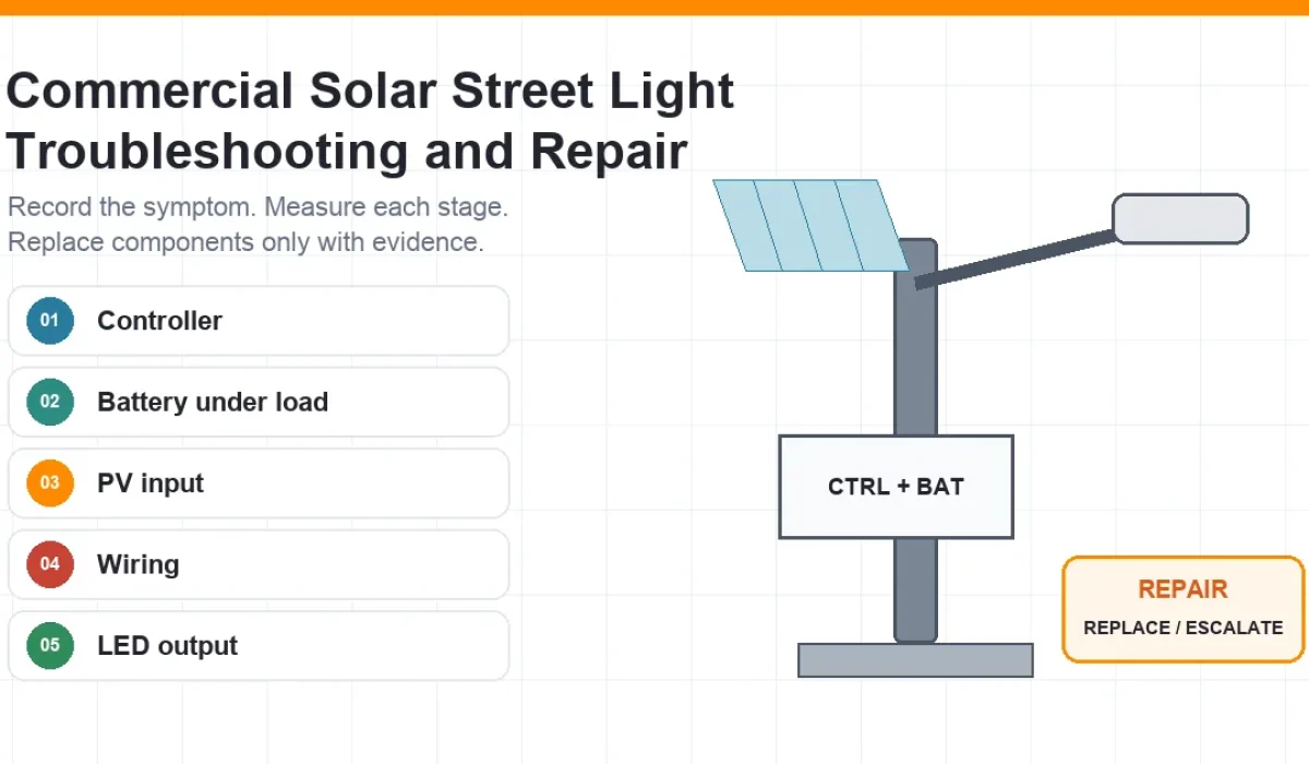
Commercial and Municipal Troubleshooting Guide
Quick Answer
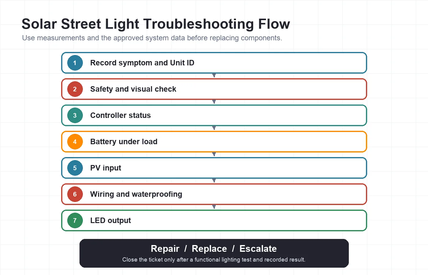
To repair a commercial solar street light, first record the exact symptom and isolate the system according to the approved controller and battery procedure. Then check the controller status, battery voltage at rest and under load, PV input during the charging window, wiring and waterproof connectors, and finally the LED output.
Compare every reading with the approved datasheet and wiring diagram. Do not replace the battery, controller or LED head by guesswork, because the same symptom can have several different causes.
Who This Guide Is For
This guide is written for EPC technicians, municipal maintenance teams, installers and project operators responsible for commercial solar street lights used on roads, public areas and infrastructure projects.
It is not intended for decorative garden lights, consumer wall lights or untrained electrical work. A separate system overview explains solar street light system components.
For small consumer products, use the DIY Solar Light Troubleshooting Checklist.
Safety Boundary Before Testing
- Only trained and authorized personnel should open, isolate or test a commercial solar street light system.
- Establish traffic control, lifting and work-at-height protection before accessing pole-mounted components.
- A PV module can continue producing voltage in daylight. Follow the approved isolation procedure.
- Do not bypass the battery management system, controller protection, fuse or approved wiring arrangement.
- Do not open, puncture or attempt field repair of a swollen, leaking, overheated, burnt or physically damaged lithium battery.
- Stop work and isolate the unit if there is evidence of burning, severe water ingress, damaged insulation or abnormal temperature.
- Before replacement, confirm voltage, polarity, current rating, connector type, communication requirements and firmware compatibility.
30-Second Diagnosis Path
A structured diagnostic sequence can reduce unnecessary component replacement and repeat site visits.
- Record the symptom and Unit ID.
- Check the controller display, indicator or fault code.
- Measure battery voltage at rest and under the intended load.
- Check PV input during the normal charging window.
- Inspect polarity, connectors, fuses, cable damage and water ingress.
- Test LED driver or lamp output only after the upstream checks are complete.
If several poles show the same fault, stop treating the issue as an isolated component failure and review the shared configuration, batch settings, site conditions and system sizing.
Start With the Exact Symptom
Common causes include power-path faults, incorrect settings, protection events, water ingress and incompatible components. The symptom determines which evidence to record first.
Completely Off
No light during the full operating period.
Turns On, Then Off
Starts normally but switches off after a short time.
Dim or Short Runtime
Output is low or operating time is shorter than expected.
Not Charging
Battery state does not recover during the charging window.
Intermittent After Rain
Fault appears after rain, humidity or temperature changes.
Several Poles Have the Same Fault
Multiple units show a similar symptom within the same project.
Table of Contents
- Who This Guide Is For
- Safety Boundary Before Testing
- 30-Second Diagnosis Path
- Start With the Exact Symptom
- Detailed Solar Street Light Repair Guide
- Step 1 – Record the Symptom and System Configuration
- Step 2 – Perform a Safe Visual Inspection
- Step 3 – Read the Controller Status and Settings
- Step 4 – Test the Battery at Rest and Under Load
- Step 5 – Check PV Input During the Charging Window
- Step 6 – Inspect Wiring and Waterproof Connections
- Step 7 – Test the LED Driver or Lamp Output
- Solar Street Light Symptom-to-Cause Checklist
- Repair, Replace or Escalate?
- Why Do Several Solar Street Lights Fail at the Same Time?
- What Not to Do During Solar Street Light Repair
- Preventive Maintenance After Repair
- Downloadable Maintenance Log
- Frequently Asked Questions
Detailed Solar Street Light Repair Guide
Work from recorded evidence and approved system data. Do not skip upstream checks because a battery, controller, wiring fault and disabled LED load can produce similar visible symptoms.
Step 1 — Record the Symptom and System Configuration
A repair decision should begin with a recorded symptom and the approved system configuration.
- Project name
- Unit ID / Pole No.
- Product model
- Battery type and nominal voltage
- Controller model
- PV module specification
- LED load
- Operating profile
- Date and weather condition
- Whether one unit or several units are affected
Different faults can produce the same visible symptom. Without the product model, approved architecture and measured values, a remote review should not identify a specific component as failed. Multiple units with the same fault should trigger a project-level check before repeated parts replacement.
Confirm that the controller, battery, PV input and LED load are electrically compatible with the approved system architecture. Do not assume that every system uses the same nominal voltage.
Step 2 — Perform a Safe Visual Inspection
A safe visual inspection should be completed before electrical measurements or component replacement.
- Burn marks
- Melted connectors
- Cable cuts
- Loose terminals
- Water ingress
- Green or white corrosion deposits
- Damaged PV junction box
- Swollen or deformed battery enclosure
- Broken seals
- Unapproved cable splices
- Loose panel or luminaire brackets
- Pole or foundation damage
Step 3 — Read the Controller Status and Settings
Controller status information can distinguish a configuration problem from a power-path or hardware fault.
- Indicator status
- Error code
- Lighting mode
- Dimming schedule
- Low-voltage protection
- Charging status
- Temperature protection
- Motion sensor settings where applicable
- Remote monitoring alarm where applicable
Do not reset or rewrite project parameters before recording the original settings. A reset may remove useful evidence and may not correct an underlying battery, PV or wiring fault.
Incorrect controller parameters can contribute to charging imbalance, excessive discharge or reduced battery service life. Review the approved settings and the operating logic of the solar street light controller.
Step 4 — Test the Battery at Rest and Under Load
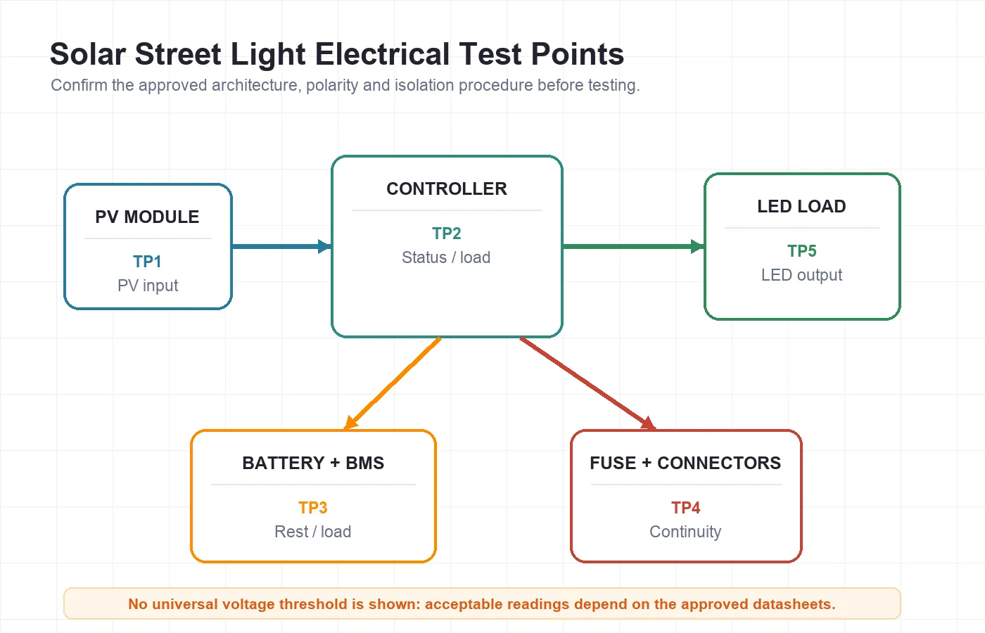
Battery voltage at rest is not enough to confirm battery health; the battery should also be evaluated under the intended load and against the manufacturer’s criteria.
- Record resting voltage
- Apply intended lighting load
- Record voltage response
- Observe BMS or protection status
- Compare with approved datasheet
- Check temperature
- Review charging history where available
A battery may appear normal at rest but drop sharply under load because of reduced capacity, internal resistance, protection activation, temperature or connection problems. Chemistry, temperature, depth of discharge, BMS status, capacity testing, load response and manufacturer criteria should guide the decision; do not use one threshold or replacement age for every battery.
Low-voltage systems also require architecture-specific review. See the 3.2V low-voltage solar lighting architecture without assuming that every project uses that platform.
Step 5 — Check PV Input During the Charging Window
PV input should be checked during a suitable charging period and compared with the approved system design.
- Shading
- Dust and bird droppings
- Panel damage
- Junction-box damage
- Connector corrosion
- Cable continuity
- PV voltage/current where authorized
- Controller charging indication
- Incorrect orientation or tilt
- New buildings, trees or signs causing shade
PV orientation should follow the approved project design. In general, panels face toward the equator, but the final azimuth and tilt must consider hemisphere, latitude, seasonal objective, local shading and mounting constraints. A voltage reading alone does not prove that the PV module can deliver the required charging current under the actual condition.
Step 6 — Inspect Wiring and Waterproof Connections
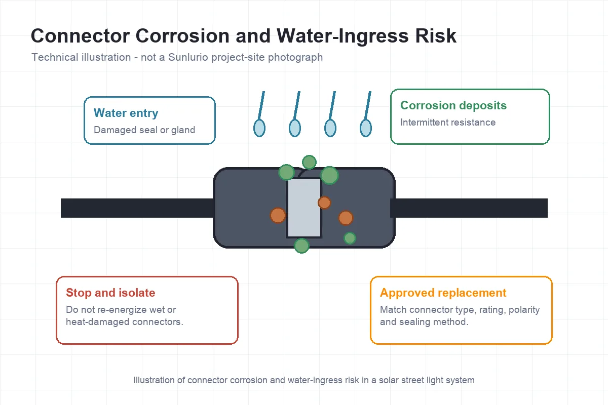
Wiring faults are often intermittent, especially when connectors have been exposed to water, heat, vibration or field modifications.
- Polarity
- Connector seating
- Pin damage
- Fuse condition
- Cable abrasion
- Moisture
- Corrosion
- Heat damage
- Improvised splices
- Cable gland sealing
Follow the approved wiring diagram and manufacturer-defined connection and disconnection sequence. Do not apply one universal sequence to every controller architecture. Connection and disconnection sequences vary by controller and system architecture. Follow the approved wiring diagram and the controller and battery manufacturer’s instructions. Confirm polarity and rated voltage before energizing the system.
Step 7 — Test the LED Driver or Lamp Output
The LED head should be tested after the controller, battery, PV input and wiring path have been checked.
- Controller load output
- Driver input/output where applicable
- Connector integrity
- Water ingress
- Overtemperature
- LED module damage
- Correct lamp power and voltage compatibility
A lamp may remain off because the controller has disabled the load, the battery protection has activated, the wiring path is open or the driver has failed. Record electrical evidence before describing the LED head as failed.
Could the Failure Be Related to the Original Installation?
Review PV orientation and shading, controller settings, polarity, loose connectors, water ingress, cable damage, mismatched components and unapproved field modifications. Foundation and soil conditions must be reviewed against the final pole reactions, project drawings, available geotechnical information and the responsible engineer’s requirements. Pole or foundation damage requires structural review. Do not erect or load the pole until the concrete has reached the strength required by the approved foundation design, project specification and responsible engineer.
Solar Street Light Symptom-to-Cause Checklist
The same symptom can have several causes, so the next action should be based on recorded evidence rather than a guessed replacement.
| Symptom | Evidence to Record | Likely Areas to Check | Next Action |
|---|---|---|---|
| Completely off | Controller status, battery under-load reading, fuse and connector condition | Battery protection, disconnected wiring, controller fault, fuse, LED load | Isolate, record readings and test each stage before replacement |
| Turns on then off | Runtime before shutdown, voltage response, controller event | Weak battery, BMS protection, low-voltage protection, incorrect profile | Compare load response and settings with approved data |
| Dim output | Brightness profile, battery state, controller output | Dimming schedule, low state of charge, driver or LED issue | Confirm settings and electrical output |
| Not charging | Midday PV reading, charging indication, shading | PV module, junction box, connector, cable or controller | Inspect and compare PV input with approved system data |
| Intermittent after rain | Moisture, corrosion, timing of fault | Connector, gland, enclosure seal, cable damage | Isolate, dry, replace damaged sealing components and retest |
| Several poles affected | Unit IDs, batch, shared settings and installation date | Common parameter, system sizing, batch wiring, site shading or environment | Escalate for project-level review |
Repair, Replace or Escalate?
The next action depends on whether the fault can be corrected with an approved field repair, requires a verified component replacement, or crosses a safety, structural or project-level boundary.
Field Repair May Be Appropriate
- Cleaning a shaded or dirty PV module
- Reseating an approved connector
- Replacing a damaged connector or fuse with an approved equivalent
- Correcting authorized controller settings
- Restoring waterproof sealing
- Repairing protected cable routing according to the approved drawing
Component Replacement May Be Required
- Battery fails the applicable manufacturer test
- Controller remains faulty after inputs and wiring are confirmed
- LED driver or module fails electrical testing
- Connector has severe heat or corrosion damage
- Enclosure, gland or junction box cannot be resealed reliably
Stop and Escalate
- Swollen, leaking, burnt or overheated lithium battery
- Repeated fault across several poles
- Unknown wiring or incompatible components
- Severe water ingress
- Structural pole, foundation or anchor-bolt damage
- Missing datasheet or wiring diagram
- Fault remains after controlled testing
Why Do Several Solar Street Lights Fail at the Same Time?
A repeated fault across several poles usually requires a project-level review of shared conditions before more components are replaced.
- Common controller parameter
- Incorrect batch wiring
- Battery/PV sizing mismatch
- Shared shading condition
- Seasonal weather assumptions
- Repeated waterproofing defect
- Wrong operating schedule
- Component compatibility
- Transport or storage issue
- Unapproved field modification
Replacing the same component on every pole without identifying the common cause can create repeated failures and unnecessary site visits. For a grouped review, request a project troubleshooting review.
What Not to Do During Solar Street Light Repair
Unsafe shortcuts can destroy evidence, damage compatible components or turn an electrical fault into a safety incident.
- Do not bypass the BMS, fuse or controller protection.
- Do not short-circuit the PV module or battery for testing.
- Do not assume one wiring sequence applies to every controller.
- Do not mix battery chemistry, voltage or controller type without verification.
- Do not replace the LED head before checking controller output and wiring.
- Do not re-energize wet, corroded or heat-damaged connectors.
- Do not open or attempt field repair of a damaged lithium battery.
- Do not reset controller parameters before recording the original configuration.
- Do not close a repair ticket without a functional lighting test and recorded result.
- Do not describe a component as failed without measurements or visible evidence.
Preventive Maintenance After Repair
Preventive maintenance should preserve measured evidence, verify the operating profile and detect repeated faults before the next service visit.
- Record Unit ID
- Record before/after measurements
- Clean PV surface as required by environment
- Inspect connectors and glands
- Check controller alarms
- Review battery load response
- Check fasteners and enclosure seals
- Inspect corrosion and water ingress
- Confirm operating profile
- Perform a night functional test
- Reinspect repeated faults
Inspection frequency should follow the project O&M plan, site environment, weather exposure, equipment instructions and observed failure history.
Downloadable Maintenance Log
A structured log helps keep commissioning data, measurements, preventive maintenance and repair history connected to the correct Unit ID.
Download the Solar Street Light Handover & Maintenance Log
Adapt the log fields to the final project model, approved wiring diagram, operating profile and maintenance responsibilities. The template does not replace project approval or the final O&M plan.
Need Help With Repeated Solar Street Light Failures?
If several poles show the same fault, send the project model, Unit IDs, controller status, battery readings, PV measurements, wiring diagram and available repair records for a structured review.
Frequently Asked Questions
These answers define the minimum evidence and compatibility checks for common commercial solar street light faults.
What should I check first when a solar street light is completely off?
Record the controller status, then check the battery under the intended load, the PV charging input, fuses, polarity, waterproof connectors and LED output. Follow the approved isolation and wiring procedures before testing.
Can a solar street light battery look normal at rest but still be faulty?
Yes. A battery may show an acceptable resting voltage but drop sharply under load because of reduced capacity, internal resistance, temperature, protection activation or a poor connection. Compare the result with the applicable battery data and test procedure.
Why does a solar street light turn on and then switch off?
Possible causes include battery voltage collapse under load, BMS or low-voltage protection, incorrect controller settings, an excessive lighting profile, wiring resistance or a driver fault. Record the shutdown time and measured values before replacing components.
Can I replace the controller or battery with any model of the same voltage?
No. Nominal voltage alone does not confirm compatibility. Battery chemistry, charging profile, current rating, PV input, LED load, connectors, communication and firmware requirements must also match the approved system.
Why are several solar street lights failing at the same time?
A repeated fault across several poles may indicate a common controller setting, batch wiring issue, system-sizing mismatch, shared shading condition, environmental exposure or component-compatibility problem. The project should be reviewed as a group rather than as isolated failures.
What information should I send for a solar street light troubleshooting review?
Send the project location, product model, Unit IDs, exact symptoms, controller status or fault codes, battery readings at rest and under load, PV measurements, wiring diagram, photos of connectors and any available repair history.