SL-SPL-HC SERIES

SL-SPL-HC Split Solar Street Light System

Split solar street lights for projects that need independent PV placement, above-ground battery access and flexible luminaire positioning.

60–120 W configurations support municipal roads, rural infrastructure, industrial access roads and EPC projects. Final PV, battery and optics are selected from the road layout, operating profile and local solar conditions.

60–120 W · LiFePO₄ · MPPT · System efficacy ≥200 lm/W · Independent PV placement

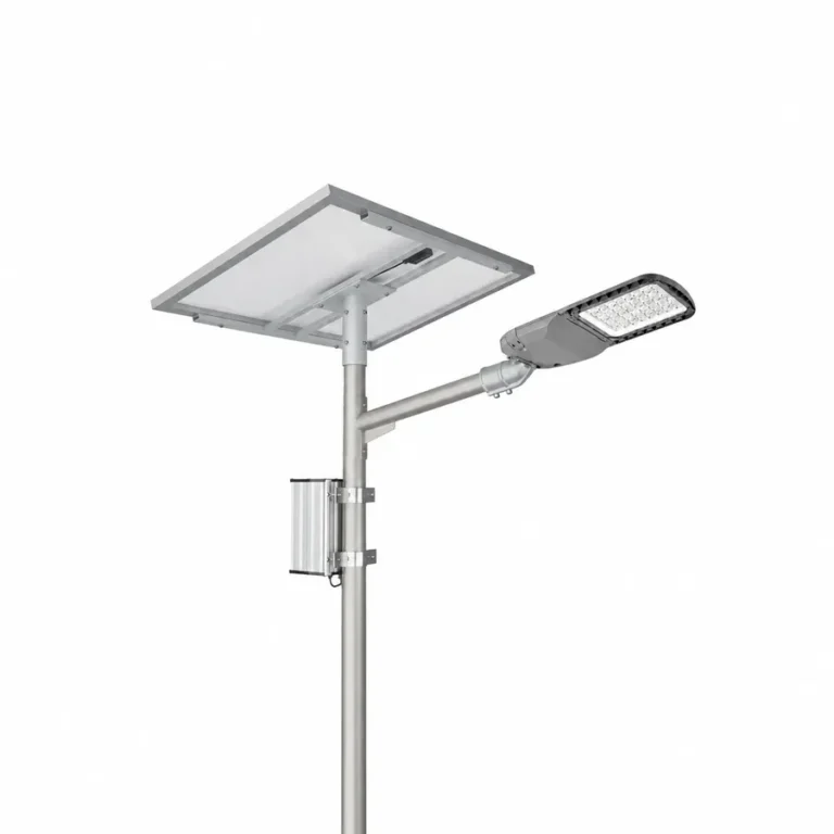
SL-SPL-HC split solar street light with PV module underside, pole-mounted external enclosure and road luminaire.
Representative split-system arrangement

SL-SPL-HC Series at a Glance

The four SL-SPL-HC models use the same split-system concept, while PV and battery capacity vary with power level and project conditions.

LED Power Range
60–120 W

Four reference output levels for road, access-road and infrastructure lighting projects.

Battery Platform
12.8 / 25.6 V

12.8 V for the 60 W reference; 25.6 V for the higher-output reference models.

PV Module Range
100–250 W

Monocrystalline modules selected for worst-month solar resource and battery recovery.

Final module efficiency follows the approved PV datasheet.

Battery Chemistry
LiFePO₄

Long-cycle battery selection; cycle-life data follows the selected battery specification.

Charge & Lighting Control
MPPT

MPPT charging with programmed lighting schedules; smart-control options where specified.

Warranty
5 Years

For the supplied system under the agreed configuration and written warranty terms.

Choose Your SL-SPL-HC Model

Use the table to shortlist a luminaire platform. Final selection depends on road geometry, optics, operating profile and the solar-energy calculation.

ModelLED PowerReference Luminous Flux*Battery PlatformReference PVReference Battery EnergyLuminaire Body Size
L × W × H (mm)
Reference Mounting Height**
SL-SPL-HC-6060 W12,000 lm12.8 V120 W80 Ah / 1,024 Wh552 × 200 × 103 mm6–8 m
SL-SPL-HC-8080 W16,000 lm25.6 V150 W55 Ah / 1,408 Wh614 × 250 × 100 mm8–10 m
SL-SPL-HC-100100 W20,000 lm25.6 V200 W65 Ah / 1,664 Wh614 × 250 × 100 mm9–12 m
SL-SPL-HC-120120 W24,000 lm25.6 V250 W80 Ah / 2,048 Wh681 × 260 × 103 mm10–14 m

SL-SPL-HC-60

60 W LED · 12,000 lm reference flux

Battery 12.8 V · reference PV 120 W

Reference battery 80 Ah / 1,024 Wh

Luminaire body 552 × 200 × 103 mm

Reference mounting height 6–8 m

SL-SPL-HC-80

80 W LED · 16,000 lm reference flux

Battery 25.6 V · reference PV 150 W

Reference battery 55 Ah / 1,408 Wh

Luminaire body 614 × 250 × 100 mm

Reference mounting height 8–10 m

SL-SPL-HC-100

100 W LED · 20,000 lm reference flux

Battery 25.6 V · reference PV 200 W

Reference battery 65 Ah / 1,664 Wh

Luminaire body 614 × 250 × 100 mm

Reference mounting height 9–12 m

SL-SPL-HC-120

120 W LED · 24,000 lm reference flux

Battery 25.6 V · reference PV 250 W

Reference battery 80 Ah / 2,048 Wh

Luminaire body 681 × 260 × 103 mm

Reference mounting height 10–14 m

* Reference luminous flux = rated LED power × 200 lm/W, using the current ≥200 lm/W system-efficacy basis. These are calculated configuration references, not measured luminous flux. Final lighting performance uses the photometric file matched to the selected luminaire and optic.

** Reference mounting-height ranges are preliminary selection guides, not road-lighting design approvals. Final pole height, spacing and optic require project photometric calculation. PV and battery pairings are preliminary and must be recalculated for the site.

Common Lighting Specifications

ParameterSpecification / Project Option
System efficacy≥200 lm/W
CCT6000 K standard; 3000 / 4000 / 5000 / 6500 K project options
Optical distributionType II / Type III / Type IV options; select with matched photometry
Photometric filesModel- and optic-matched IES / LDT, requested for engineering review
DimmingTime control, light control and programmable schedules
Ingress protectionBattery enclosure IP65; luminaire IP/IK confirmed in selected submittal
Operating temperatureConfirmed against the selected luminaire, battery and controller

Configure the Energy System for the Project

LED wattage alone cannot determine PV and battery size.
Review the nightly operating profile, autonomy target, usable battery energy and worst-month solar conditions together.

SL-SPL-HC-60
60 W LED

Reference PV
120 W

Battery Platform
12.8 V

Reference Battery
80 Ah

Nominal Energy
1,024 Wh

Preliminary energy configuration. Recalculate for the actual operating profile and solar resource.

SL-SPL-HC-80
80 W LED

Reference PV
150 W

Battery Platform
25.6 V

Reference Battery
55 Ah

Nominal Energy
1,408 Wh

Preliminary energy configuration. Recalculate for the actual operating profile and solar resource.

SL-SPL-HC-100
100 W LED

Reference PV
200 W

Battery Platform
25.6 V

Reference Battery
65 Ah

Nominal Energy
1,664 Wh

Preliminary energy configuration. Recalculate for the actual operating profile and solar resource.

SL-SPL-HC-120
120 W LED

Reference PV
250 W

Battery Platform
25.6 V

Reference Battery
80 Ah

Nominal Energy
2,048 Wh

Preliminary energy configuration. Recalculate for the actual operating profile and solar resource.

Inputs Required for Energy Sizing

Nightly Operating Profile

Total operating hours and the power level needed in each time period.

Dimming Schedule

Confirm the output schedule rather than assuming full rated power all night.

Autonomy Target

Define reserve operation and minimum light output during low-solar periods.

Worst-Month Solar Resource

Use site irradiation and shading, not an annual-average assumption.

Temperature & System Losses

Allow for battery temperature, wiring, conversion, ageing and other losses.

Controller / Communication Demand

Include controls and communications loads where applicable.

Engineering Example

Why energy margin matters

In the illustrative 80 W dimming example, 150 W PV × 4.5 sun hours × 80% yield gives 540 Wh/day. LED-only demand is 80 W × 6.5 equivalent full-power hours, or 520 Wh/night. The 20 Wh/day margin disappears if auxiliary loads, losses or a poorer solar month increase demand or reduce generation.

This is an illustrative balance, not a site yield or autonomy guarantee. Extended 4–5-night reserve needs a new PV, battery and operating-profile calculation.

Independent PV & Battery Placement

A split architecture allows PV orientation, luminaire aiming and above-ground energy access to be planned separately within one coordinated pole and cable system.

Road Luminaire

Die-cast aluminium road luminaire with a replaceable internal light-source assembly. Optic and output are selected for the road layout and photometric requirement.

External PV Module

High-efficiency monocrystalline PV module with project-selected power and support arrangement. Orientation and tilt are reviewed for local solar access and shading.

Above-Ground Battery & Controller

LiFePO₄ battery and MPPT controller in an external above-ground enclosure for inspection and component access. The specified battery enclosure is IP65.

When a Split System Makes Sense

Independent solar orientation: PV tilt and direction can be set separately from light aiming. Accessible energy components: above-ground placement supports inspection planning. Flexible energy sizing: separate PV and battery components can be specified for the site’s operating profile.
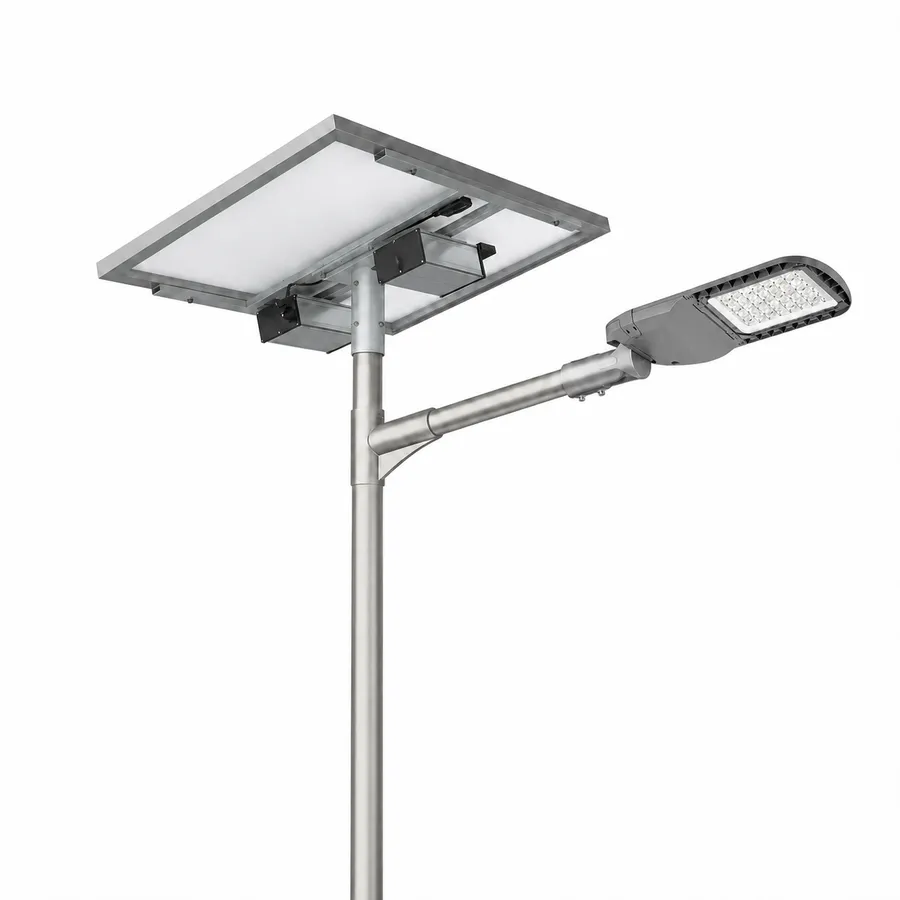
SL-SPL-HC split solar street light with PV module underside, support bracket, under-panel enclosures and LED road luminaire on a pole.
Under-panel enclosure arrangement. Final components follow the approved project drawing.

Battery at the PV Support

Plan the module, bracket and enclosure together. Check support loads, access clearances, shading and cable protection against the project drawing.

Pole-Mounted Battery Enclosure

Set an accessible above-ground position and confirm clamp capacity, cable route and the maintenance approach. This series does not use an underground battery arrangement.
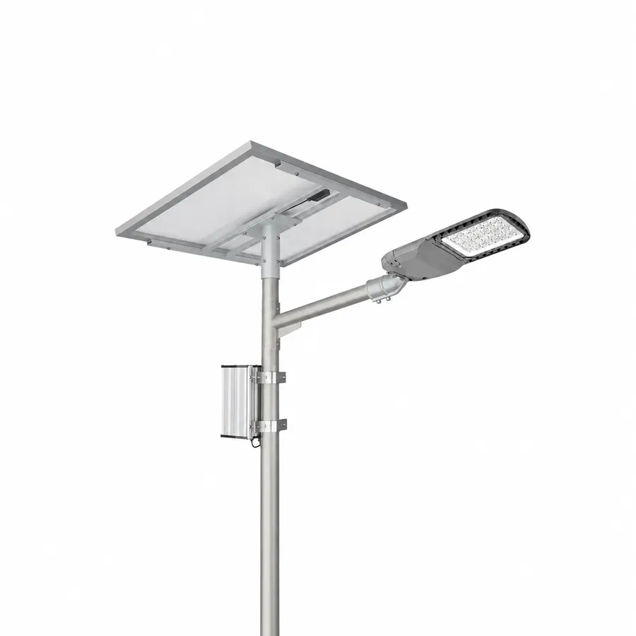
SL-SPL-HC split solar street light with PV module underside, pole-mounted external enclosure and LED road luminaire.
Pole-mounted enclosure arrangement. Final component specification follows the project design.
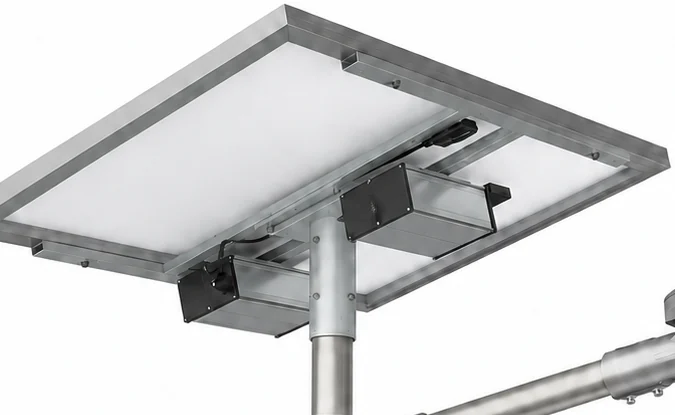
SL-SPL-HC PV support underside with bracket and under-panel enclosure mounting positions.
PV Support & Enclosure Mounting Detail — exterior view.

Detail view: the PV support and exterior enclosure positions. Internal assembly and final bracket geometry follow the approved component and project drawings.

Lighting & Optical Configuration

Road-lighting performance depends on more than LED wattage. Luminaire efficacy, optical distribution, mounting height, pole spacing and matched photometry must be reviewed together.

System efficacy≥200 lm/W; final performance follows matched photometric data
LED packages5050 / 5054 / 7070, selected for the order
CCT6000 K standard; 3000 / 4000 / 5000 / 6500 K options
Optical distributionType II / Type III / Type IV options; matched optic required
DimmingTime and light control with a programmable output schedule
Design fileIES / LDT matched to model, optic and output setting; requested for engineering review

Project Lighting Design Inputs

Road Geometry

Road width, carriageway, pedestrian areas and luminaire arrangement.

Mounting Height & Pole Spacing

Use project geometry rather than selecting the model from wattage alone.

Optic / Photometric File

Use the IES / LDT file matched to the selected luminaire and optic.

Target Lighting Criteria

Confirm required illuminance, uniformity or road class from the project specification.

The calculated reference flux in the model table is not measured photometry. Submit road width, pole height and spacing, outreach, aiming and target criteria for a model- and optic-matched IES / LDT and DIALux review. Check lighting at each reduced-output stage.

Mechanical & Mounting

Three die-cast aluminium luminaire body sizes cover the four models. These are lamp-head dimensions, not PV-module, battery-box or full-system dimensions.

Luminaire Body Sizes

SMALL HOUSING
552 × 200 × 103 mm

Model: SL-SPL-HC-60

LED: 60 W

Reference mounting height: 6–8 m

MEDIUM HOUSING
614 × 250 × 100 mm

Model: SL-SPL-HC-80 / 100

LED: 80 / 100 W

Reference mounting height: 80 W: 8–10 m; 100 W: 9–12 m

LARGE HOUSING
681 × 260 × 103 mm

Model: SL-SPL-HC-120

LED: 120 W

Reference mounting height: 10–14 m

Mounting & Support Check

Luminaire: side-entry or post-top; Ø60 / Ø76 / Ø83 / Ø89 mm interfaces with a matched adaptor. Adjustment is 0–30°.

PV bracket: typically 0–45° mechanical adjustment; final tilt and support are site-specific.

Battery enclosure: above-ground aluminium-alloy box, IP65 at its specified closure and cable entries.

Confirm pole strength, PV projected area, enclosure loading, bracket, fixings, grounding, cable protection and foundation for the site. No complete-system wind-speed rating or universal pole spacing is declared.
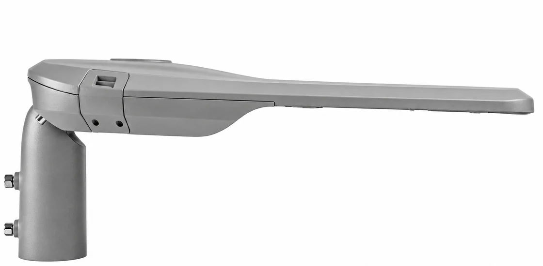
SL-SPL-HC luminaire side view showing the pole mounting interface and housing profile.
Luminaire side profile and pole interface; final adaptor follows the project drawing.

Serviceability & Maintenance

Split-system service points are separated across the luminaire, PV support and above-ground energy enclosure. These images identify exterior access locations.
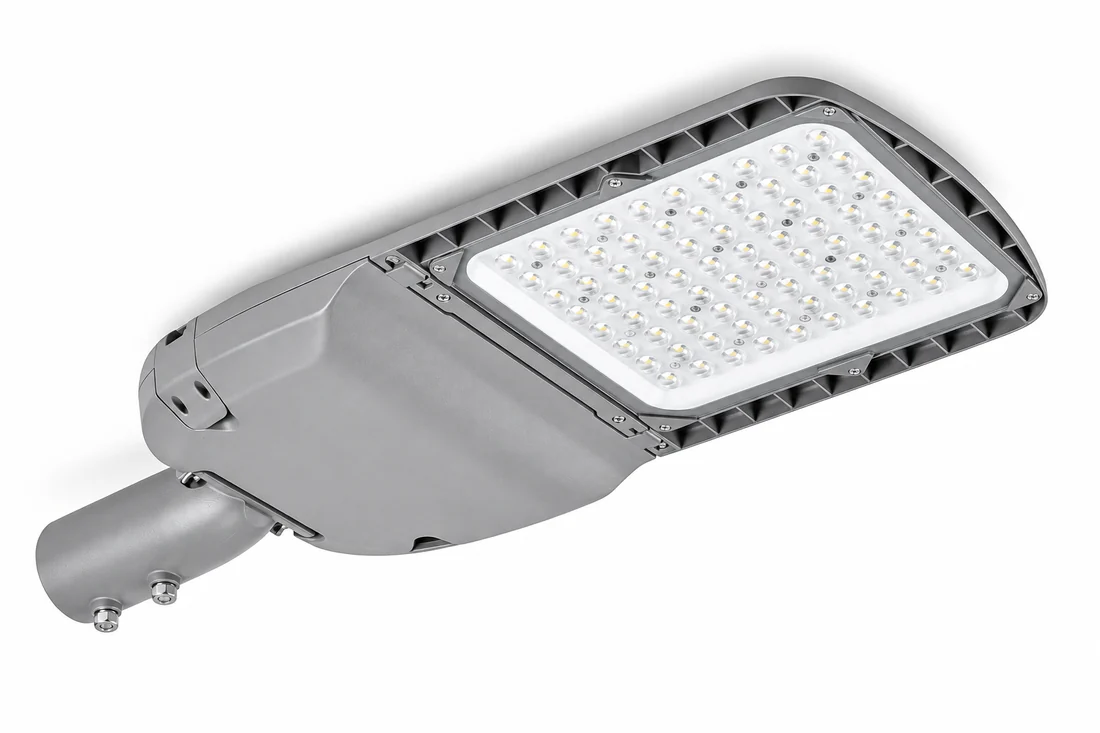
SL-SPL-HC road luminaire underside showing the optic panel and exterior housing fasteners.

Replaceable Light-Source Assembly

Matched internal assembly can be replaced while retaining an undamaged luminaire housing. Individual LED packages are not field-replacement items.
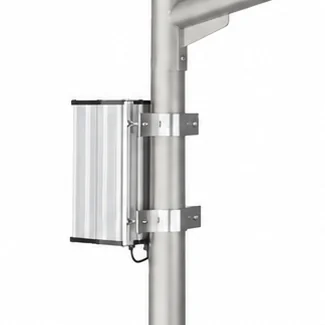
SL-SPL-HC above-ground enclosure mounted to a pole with external clamps.

Above-Ground Battery Access

Position the external battery enclosure on the pole or near the PV support for above-ground inspection and replacement planning.
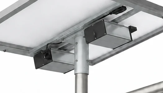
SL-SPL-HC enclosures positioned beneath the PV support on the pole.

Controller Access

The MPPT controller is housed with the battery in the external enclosure. Replacement settings must match battery, PV and LED output.

SL-SPL-HC PV support underside with bracket and under-panel enclosure mounting positions.

Independent PV Service

Inspect PV orientation, shading, module surface, support, cable route and connections separately from luminaire aiming.

Exterior views identify service locations. Internal access and replacement procedures follow the approved manual and project drawing.

TENDER & ENGINEERING FILES

Engineering Documents & Tender Support

Request files for the selected HC model, optic, PV, battery, controller and procurement stage. The submission should describe the equipment proposed for supply.

Model-Matched Datasheet

Electrical, optical and mechanical data for the selected luminaire and energy configuration.

IES / LDT & DIALux

Photometry matched to the luminaire and optic, with lighting calculations based on agreed road geometry.

Energy / Battery / PV Review

Nightly demand, worst-month solar resource, storage, reserve output and recovery reviewed together.

Drawings / BOQ / Tender Support

Mounting drawings, enclosure coordination, BOQ mapping and technical deviations for the defined supply scope.

Project documents are issued after the model and project scope are confirmed. We do not use one generic IES file or certificate set for every variant. Documents must match the actual model and supply configuration.

See photometric file support and tender and BOQ review.

SL-SPL-HC FAQ

Answers for project selection, energy sizing, installation and controlled engineering documents.

What is the main difference between a Split and All-in-One solar street light?

A Split system places the road luminaire, PV module and LiFePO₄ battery enclosure separately, so solar direction, light aiming and service access can be planned independently. An All-in-One product integrates these elements more closely. Choose the architecture from pole layout, solar exposure, maintenance access and installation scope.

Start with the nightly operating profile, dimming stages, minimum reserve output and target autonomy. Add controller and communications demand, conversion losses, usable battery capacity, temperature and ageing assumptions. Select PV from worst-month irradiation, shading, electrical compatibility and recovery after low-sun periods. The published PV and battery examples are engineering starting points only.

No. The current SL-SPL-HC series uses above-ground battery enclosures, either pole-mounted or positioned at or beneath the PV support. Confirm access, support and cable routing for the selected arrangement.

Yes. The PV bracket is typically adjustable over 0–45° for site-specific solar orientation, while the luminaire can be aimed over 0–30° for the road-lighting layout. Final settings and structural support follow the project drawing.

Yes, subject to engineering review. Request IES / LDT for the confirmed model, optic and output setting. DIALux or Relux work then uses the project road geometry, layout and target criteria. These are controlled, model-matched deliverables rather than generic public downloads.

Begin with road width, pole height and spacing, required illuminance and uniformity, operating hours, dimming, autonomy, solar conditions and the BOQ. The 60 / 80 / 100 / 120 W heights are initial guides. Confirm the final model with matched photometry and an energy calculation; wattage alone is insufficient.

Request SL-SPL-HC Project Configuration

Send the project location, road width, pole height and spacing, nightly operating profile, autonomy target and required tender files. We will review the model, PV and battery configuration, optic and document scope.

PLANNING A SOLAR STREET LIGHTING PROJECT?

Share your project location, estimated quantity and requirements.
We’ll review the suitable configuration and supply scope for your project.

Request a Project Document Pack

Share your project location, road width, pole height, spacing, working hours, backup days, and required documents. Our team can help prepare configuration guidance, datasheets, IES/LDT files, DIALux support when applicable, drawings, and BOQ matching notes.