Quick Answer
The main motion sensor settings for solar street lights are standby brightness, boost brightness, delay time, sensitivity, and day-night activation logic. Standby brightness controls the lower background light level. Boost brightness controls the higher output when movement is present. Delay time controls how long the lamp stays bright after movement.
The right setting depends on road type, traffic frequency, pole height, sensor direction, PIR or radar behavior, battery capacity, solar charging input, and project safety requirements. These settings should not be copied from one default remote-control mode to every project. They should be treated as starting points, then checked through testing, autonomy review, and commissioning records.
Project Review Summary
| Item | Project Review Point |
|---|---|
| Main topic | Solar street light motion sensor settings |
| Best-fit buyers | EPC contractors, municipal project teams, distributors, installers, and tender buyers |
| Best-fit projects | Rural roads, village roads, campuses, pathways, compounds, parking areas, industrial access roads, and low-traffic municipal roads |
| Core search intent | How to set standby brightness, boost brightness, delay time, sensitivity, and light-level threshold for motion sensor solar street lights |
| Main decision factor | Road safety, traffic pattern, sensor behavior, battery autonomy, and commissioning record |
| Key settings | Standby brightness, boost brightness, delay time, sensitivity, light-level threshold, sensor type, trigger behavior, and final controller profile |
| Required checks | Pole height, road width, sensor direction, false triggering risk, rainy-season margin, and handover requirement |
| Common mistake | Using one default motion sensor mode for every road type without checking battery autonomy or public visibility |
What Are Motion Sensor Settings in Solar Street Lights?
Motion sensor settings control how a solar street light behaves when the road is quiet and when movement is present.
In most project discussions, motion sensor mode includes:
- Standby brightness.
- Boost brightness.
- Delay time.
- Sensor sensitivity.
- Light-level threshold or day-night activation logic.
- Sensor type.
- Sensor direction.
- Detection distance.
- Trigger sensitivity.
- Return-to-standby behavior.
- Controller profile.
- Timer and motion combination.
- Final operating mode.
The motion sensor itself is only one part of the system. The actual lighting result depends on how the sensor works together with the controller, battery, solar panel, dimming profile, and road environment.
A solar street light with a motion sensor can still perform poorly if the standby brightness is too low, boost brightness is too aggressive, delay time is too long, sensitivity is too high, or false triggering happens too often.
Common Motion Sensor Operating Modes
Different solar street light controllers may use different names for motion sensor modes. In project discussions, the most common operating logic includes motion-only mode, dim-to-bright mode, dusk-to-dawn mode, and hybrid timer plus motion mode.
| Mode | How It Works | Project Review |
|---|---|---|
| Motion-only mode | The lamp stays off or nearly off during quiet periods and boosts when movement is present | Saves energy, but may not be suitable for public roads because background visibility is very low |
| Dim-to-bright mode | The lamp stays at standby brightness and boosts when movement is present | Often practical for low-traffic roads because it balances visibility and energy saving |
| Dusk-to-dawn or constant mode | The lamp runs according to a fixed brightness profile after dusk, with motion sensor disabled or less important | More predictable for public roads, but energy consumption must be checked |
| Hybrid timer plus motion mode | The lamp uses timer-based brightness during active hours and motion boost during low-traffic hours | Often useful for projects that need both predictable visibility and battery autonomy |
For most EPC and municipal projects, dim-to-bright or hybrid timer plus motion mode is usually more practical than pure motion-only mode.
Motion-only mode may be acceptable for private, low-risk, low-traffic areas. It is usually not preferred for public roads, school roads, municipal roads, or residential access roads because the road may become too dark before the sensor responds.
Recommended Starting Settings by Road Type
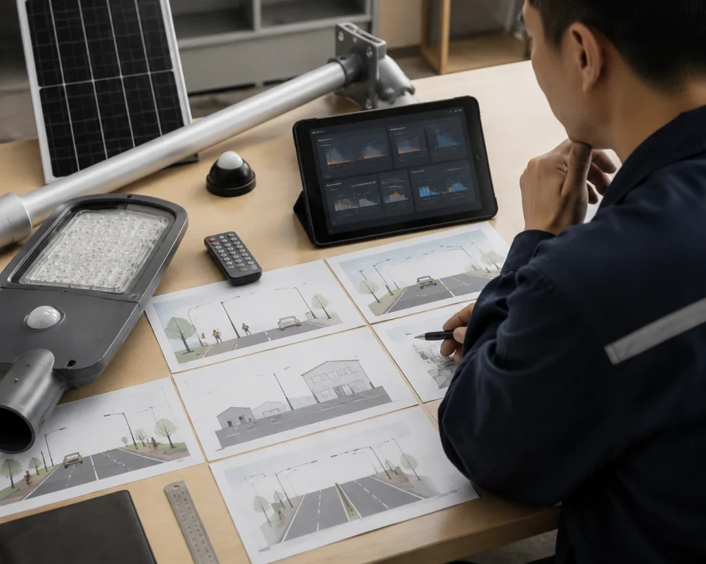
The table below gives starting review directions for common project types. These values are not fixed design rules. Final settings should be checked against pole height, road width, traffic frequency, battery capacity, dimming profile, rainy-season autonomy, and project acceptance requirements.
| Road / Area Type | Starting Standby Brightness | Starting Boost Brightness | Delay Time Direction | Sensitivity Direction | Review Note |
|---|---|---|---|---|---|
| Pedestrian pathway | 10–30% | 60–100% | Short to medium | Medium | Avoid making the path completely dark before detection |
| Village road | 20–40% | 80–100% | Medium | Medium | Balance basic visibility and battery autonomy |
| School road | 30–50% or timer-based evening profile | 80–100% | Medium | Medium | Predictable visibility is more important than maximum saving |
| Campus road | 20–50% | 80–100% | Medium | Medium | Review both pedestrian and low-speed vehicle movement |
| Parking lot | 20–50% | 80–100% | Medium to long | Medium to high | Check false triggering and frequent vehicle movement |
| Parking entrance | 30–50% | 80–100% | Medium to long | Project-specific | Vehicle response timing is more important than maximum distance |
| Industrial access road | 30–50% or hybrid mode | 100% if required | Medium to long | Project-specific | Review shift traffic and worker safety |
| Rural access road | 10–40% | 80–100% | Medium | Medium | Check detection timing and rainy-season autonomy |
| Main municipal road | Timer or hybrid mode preferred | Project-specific | Project-specific | Project-specific | Pure motion-only mode is usually not the best option |
These starting ranges should be used for project review, not as universal settings. A public municipal road, school road, compound road, and private farm road may all need different safety and autonomy margins.
Step-by-Step Motion Sensor Setting Workflow
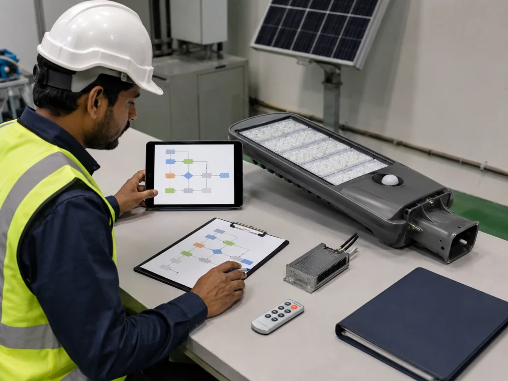
A practical motion sensor setting process should follow the project condition, not only the remote-control default mode.
Step 1: Confirm the Road Type and Traffic Pattern
Start by identifying the real application:
- Pedestrian pathway.
- School road.
- Village road.
- Campus road.
- Parking lot.
- Parking entrance.
- Industrial access road.
- Rural access road.
- Main municipal road.
- Compound or private road.
The traffic pattern decides whether pure motion mode is practical or whether timer mode or hybrid timer plus motion mode is safer.
Step 2: Choose the Operating Mode
Select the basic control logic first:
- Motion-only mode.
- Dim-to-bright mode.
- Dusk-to-dawn or constant mode.
- Hybrid timer plus motion mode.
For public roads and municipal roads, dim-to-bright or hybrid mode is usually safer than motion-only mode because background visibility remains available.
Step 3: Set Standby Brightness First
Standby brightness defines the lowest visible background lighting level. It should not be set only for maximum energy saving.
Check:
- Whether pedestrians can recognize the road edge.
- Whether the road feels safe before motion boost.
- Whether the owner expects visible light throughout the night.
- Whether standby brightness still supports battery autonomy.
Step 4: Set Boost Brightness Based on Required Visibility
Boost brightness should match the application, not only the product maximum output.
Check:
- Road width.
- Pole spacing.
- User type.
- Pedestrian or vehicle movement.
- Safety requirement.
- Whether full output is truly needed.
Boost brightness is often set high for demonstration, but that may not be the best long-term operating profile.
Step 5: Adjust Delay Time Based on Movement
Delay time should match how people or vehicles move through the area.
Check:
- Pedestrian walking speed.
- Vehicle speed.
- Distance between poles.
- How long the road should remain bright after movement.
- Whether long delay will drain the battery during frequent traffic.
Step 6: Adjust Sensitivity and Sensor Direction
Sensitivity should match the target road area. It should not automatically be set to the highest level.
Check:
- Whether the sensor responds before the user reaches the darker area.
- Whether it responds to adjacent road traffic.
- Whether trees, animals, reflective surfaces, or moving objects trigger the lamp.
- Whether PIR or radar behavior is suitable for the site.
Step 7: Check LUX or Day-Night Activation Logic
Some controllers call this LUX. Others use photocell logic, solar panel voltage detection, time logic, or controller profile settings.
Check:
- Whether the lamp turns on correctly after dusk.
- Whether it stays off during daytime charging.
- Whether cloudy daytime conditions cause abnormal behavior.
- Whether the sensor mode becomes active at the correct time.
Step 8: Test Before Pole Installation
Test the profile at ground level whenever possible.
The test should confirm:
- Standby brightness.
- Boost brightness.
- Delay time.
- Sensitivity.
- Return-to-standby behavior.
- Day-night activation logic.
- Final controller profile.
Step 9: Record the Final Controller Profile
After adjustment, record the final settings by pole number or project zone.
The record should include:
- Sensor type.
- Standby brightness.
- Boost brightness.
- Delay time.
- Sensitivity or trigger level.
- Controller profile.
- Test result.
- Correction status.
Step 10: Recheck After Several Nights When Smart Control Is Available
For larger projects with smart control, review real operation after several nights. This helps confirm whether the profile behaves correctly under actual traffic and weather conditions.
Sensitivity, Delay Time, and Light-Level Threshold
Some solar street light controllers, remote controls, or smart platforms describe motion sensor settings with terms such as sensitivity, time, and lux. The exact names may vary by controller brand or system design, but the project review logic is similar.
| Setting | Common Name | What It Controls | Project Review Point |
|---|---|---|---|
| Sensitivity | SENS, sensitivity, trigger sensitivity | How easily the sensor responds to movement and sometimes the practical detection distance | Higher sensitivity may improve response but can also increase false triggering |
| Delay time | TIME, delay time, hold time, boost duration | How long the lamp stays at boost brightness after movement is present | Longer delay improves comfort but increases battery consumption |
| Light-level threshold | LUX, light threshold, photocell logic, day-night logic | How dark the environment must be before the light or sensor mode becomes active | Incorrect logic may cause early activation, late activation, or abnormal daytime behavior |
Sensitivity should not be set only to the maximum level. If sensitivity is too high, the lamp may respond to nearby road activity, moving branches, animals, reflective surfaces, or movement outside the target area. This can keep the lamp at boost brightness too often and reduce battery autonomy.
Delay time should be reviewed together with standby brightness and boost brightness. A longer delay time can improve visibility and user comfort, but it may drain the battery faster when traffic is frequent.
Light-level threshold should be reviewed carefully because different solar street light controllers may use different day-night logic. Some systems use photocell logic, some use solar panel voltage, and some use controller profile settings. The goal is to make sure the lamp activates at the correct time after dusk and does not behave abnormally during cloudy daytime conditions.
Standby Brightness, Boost Brightness, and Delay Time Explained
The three most important settings in a motion sensor profile are standby brightness, boost brightness, and delay time.
Standby Brightness
Standby brightness is the lower lighting level used when no movement is present.
It provides background visibility and determines how much energy the lamp consumes during quiet periods. A very low standby level may save more energy, but it may make the road feel unsafe. A higher standby level improves background visibility, but it increases battery consumption.
Standby brightness should be reviewed based on:
- Road type.
- Public safety requirement.
- User comfort.
- Pole spacing.
- Mounting height.
- Road width.
- Ambient darkness.
- Security requirement.
- Battery autonomy requirement.
- Rainy-season condition.
Boost Brightness
Boost brightness is the higher lighting level used when movement is present.
It is designed to improve visibility when pedestrians, vehicles, or site users enter the sensor response area.
Boost brightness should be reviewed based on:
- Required visibility.
- Traffic type.
- Pedestrian or vehicle movement.
- Road safety requirement.
- Battery capacity.
- Delay time.
- Trigger frequency.
- Pole spacing.
- Luminaire output.
- Project acceptance standard.
Boost brightness that is too low may not provide enough visibility when movement is present. Boost brightness that is too high may consume too much battery power if the sensor triggers frequently.
Delay Time
Delay time means how long the solar street light remains at boost brightness after movement is present.
A longer delay time can improve comfort and visibility because the lamp stays bright for a longer period. However, it also increases energy use. A shorter delay time can save energy, but it may cause the lamp to return to standby too quickly.
Delay time should be reviewed together with:
- Pedestrian walking speed.
- Vehicle speed.
- Road length.
- Pole spacing.
- Traffic frequency.
- Safety requirement.
- Standby brightness.
- Boost brightness.
- Battery autonomy.
- Rainy-season margin.
- Sensor type.
These settings cannot be reviewed separately. If standby brightness is low, boost response becomes more important. If boost brightness is high, delay time becomes more important for battery protection. If sensitivity is too high, the lamp may enter boost mode too often.
For broader dimming logic, see Sunlurio’s guide to solar street light dimming profile and battery autonomy.
PIR and Radar Settings May Behave Differently
PIR and radar sensors may need different setting reviews.
PIR sensors respond to infrared heat changes from moving people, animals, vehicles, or other warm objects. They are often used for pathways, parks, compounds, school roads, village roads, and low-speed pedestrian areas.
Radar sensors detect movement through signal reflection changes. They may provide wider or longer detection behavior depending on the sensor model, mounting height, direction, and sensitivity setting.
For PIR sensor settings, review:
- Sensor direction.
- Mounting height.
- Movement angle.
- Thermal background.
- Pedestrian comfort.
- Whether the sensor responds early enough.
- Whether the road still has enough standby visibility.
For radar sensor settings, review:
- Sensitivity.
- Detection direction.
- Road geometry.
- Nearby movement sources.
- Reflective surfaces.
- Vehicle movement.
- False triggering risk.
- Battery impact from frequent boost.
Radar is not automatically better than PIR. PIR is not automatically enough for every road. The best setting depends on project behavior.
For sensor selection, see Sunlurio’s guide to PIR vs radar motion sensors for solar street lights.
Motion Sensor Settings by Road Type
| Road or Area Type | Suggested Review Direction | Key Risk |
|---|---|---|
| Pedestrian pathway | Moderate standby visibility and comfortable boost response | Standby too low may feel unsafe |
| School road | Predictable lighting and safe response timing | Boost too late or delay too short |
| Village road | Balance cost, autonomy, and basic visibility | Overly aggressive energy saving |
| Campus road | Mixed pedestrian and low-speed vehicle movement | Inconsistent response between poles |
| Parking lot | Vehicle movement and walking comfort | False triggering and battery drain |
| Parking entrance | Earlier vehicle response may be needed | Delay time and sensitivity mismatch |
| Industrial access road | Shift-based vehicle and worker activity | Frequent boost during operation hours |
| Compound road | Security and comfort matter | Background lighting too low |
| Rural access road | Low traffic and autonomy matter | Detection too late or range mismatch |
| Main municipal road | Timer or hybrid mode may be better | Constant traffic reduces motion saving |
This table is not a fixed design rule. It is a project review starting point.
For roads with steady traffic, timer mode or hybrid timer plus motion mode may be more predictable than pure motion sensor mode. For the control mode comparison, see motion sensor vs timer mode for solar street lights.
Common Setting Risks That Affect Complaints and Battery Autonomy
Motion sensor complaints usually come from two sides: the road feels too dark, or the battery does not last long enough. Both problems are often caused by profile settings, not only by sensor quality.
Standby Brightness Too Low
Very low standby brightness may save energy, but it can create safety and comfort complaints.
Common problems include:
- The road looks too dark before the sensor triggers.
- Pedestrians feel unsafe during standby periods.
- Drivers cannot see the road edge clearly.
- Security staff request higher background brightness.
- The owner thinks the lamp is not working properly.
- Public users report uneven lighting.
For private compounds, farms, or low-use access roads, lower standby brightness may be acceptable. For public roads, campuses, school access roads, or residential project roads, background visibility may be more important.
Boost Brightness Too High
Boost brightness improves visibility, but it also increases energy consumption. If the light frequently enters boost mode, the system may use much more power than expected.
High boost brightness becomes a risk when:
- Traffic is frequent.
- Delay time is long.
- Radar sensitivity is too high.
- The site has false triggering.
- The project has long cloudy or rainy periods.
- Battery capacity is limited.
- Solar charging input is weak.
- Standby brightness is already high.
- Multiple lamps are triggered repeatedly.
Boost brightness should not be selected only to make the lamp look brighter during demonstration. It must be checked against real operating hours and battery autonomy.
Delay Time Too Long
Long delay time keeps the lamp bright for a longer period. This can improve comfort, but it can also reduce battery autonomy.
Delay time becomes risky when:
- Traffic is frequent.
- Multiple poles are triggered in sequence.
- Standby brightness is already high.
- Boost brightness is set close to full output.
- The project needs several nights of autonomy.
- Rainy-season solar charging is limited.
A short delay is not always better either. If the light returns to standby too quickly, users may feel the road is unstable or uncomfortable. The delay should match the real movement pattern.
False Triggering and Frequent Boost
False triggering means the lamp enters boost mode even when useful road movement is not present.
Frequent boost means the lamp enters high brightness too often, even if the trigger is technically real.
Both problems reduce the energy-saving benefit of motion sensor mode.
Common causes include:
- Sensor direction too wide.
- Radar sensitivity too high.
- Tree movement.
- Animals.
- Moving signs or banners.
- Adjacent road traffic.
- Reflective surfaces.
- Industrial equipment movement.
- Nearby building activity.
- Parking lot movement outside the intended area.
If false triggering or frequent boost continues for hours, the battery may drain faster than expected. This may cause the lamp to dim early, shut down early, or enter controller protection after cloudy or rainy days.
For failure review after bad weather, see why solar street lights stop working after cloudy or rainy days.
Motion Mode Used on the Wrong Road Type
Motion sensor mode saves energy only when the lamp spends enough time in standby brightness.
It may not save much energy when:
- The road has constant traffic.
- The sensor triggers too frequently.
- Delay time is too long.
- Boost brightness is too high.
- Standby brightness is already high.
- Sensitivity is too high.
- The site has false triggering.
- Multiple poles are triggered in sequence all night.
- The project uses motion mode on a road that should use timer mode.
For high-traffic roads or public municipal roads, timer mode or hybrid mode may provide more predictable performance.
Hybrid Timer Plus Motion Mode May Be Better
For many projects, the best solution is not pure motion sensor mode. Hybrid timer plus motion mode may be more practical.
A hybrid profile may use:
- Stable timer-based lighting during active evening hours.
- Lower standby brightness during late-night low-traffic periods.
- Motion-triggered boost when people or vehicles are present.
- More conservative settings during rainy seasons.
- Different profiles by road zone.
Hybrid mode can help balance public visibility and battery autonomy.
It is especially useful when early evening traffic is active but late-night traffic becomes low. It can also reduce the risk of setting the road too dark too early.
For the full comparison, see motion sensor vs timer mode for solar street lights.
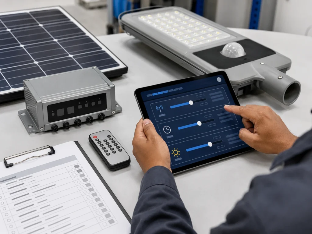
How Remote Control Is Used for Motion Sensor Settings
Remote control is often used during installation and commissioning to set or confirm motion sensor mode.
Depending on the controller and remote design, installers may use it to confirm:
- AUTO mode.
- Timer mode.
- Motion mode.
- Standby brightness.
- Boost brightness.
- Delay time.
- Sensor mode.
- Sensitivity or trigger level.
- Test mode.
- Final controller profile.
Remote control is useful for local setup, but it does not automatically prove that the whole project has consistent settings. Each pole may need to be checked and recorded.
For basic setup logic, see how to set up a solar street light with remote control.
Day-Night Activation Logic Should Be Checked
Motion sensor mode usually works together with day-night switching logic. The lamp should activate after dusk and stop operating during daytime charging.
Depending on the controller design, day-night activation may rely on:
- Photocell logic.
- Solar panel voltage detection.
- Controller time logic.
- Light-level threshold.
- Remote control preset.
- Smart platform setting.
If this logic is not suitable, the lamp may activate too early, too late, or behave abnormally during cloudy daytime conditions.
Project teams should check:
- Whether the light turns on correctly after dusk.
- Whether it stays off during daytime charging.
- Whether cloudy daytime conditions cause abnormal operation.
- Whether sensor mode becomes active at the correct time.
- Whether the final day-night logic is recorded during commissioning.
This is especially important when troubleshooting complaints such as “the lamp does not turn on,” “the lamp turns on too early,” or “the lamp behaves differently after rainy days.”
When Smart Control Helps Motion Sensor Projects
Smart control can be useful when the project has many poles or when sensor behavior needs to be reviewed after installation.
Smart control may help project teams:
- Check pole status remotely.
- Review abnormal lamps.
- Adjust profiles by zone.
- Compare different road sections.
- Monitor battery or charging status.
- Review fault alerts.
- Reduce manual inspection.
- Support maintenance planning.
- Record operation behavior after handover.
This is useful for large municipal projects, industrial parks, campuses, ports, highways, smart city roads, or remote projects where manual inspection is expensive.
For control system selection, see remote control vs smart control for solar street lights.
Africa and Middle East Project Considerations
Africa Projects
For many Africa solar street light projects, motion sensor mode is used to balance budget, battery autonomy, and nighttime visibility.
It may be useful for:
- Village roads.
- School roads.
- Farms.
- Compounds.
- Parking areas.
- Rural access roads.
- Low-traffic municipal sections.
Project teams should avoid setting standby brightness too low only to save energy. In public areas, users still need enough background visibility. For distributed village projects or municipal projects, the final profile should be consistent and easy for local maintenance teams to understand.
Middle East Projects
For Middle East projects, motion sensor settings should be reviewed together with heat, dust, long nights, maintenance distance, and battery protection.
Important checks include:
- Dust and panel soiling impact on charging.
- High-temperature impact on battery and electronics.
- Sensor false triggering from reflective surfaces or nearby road activity.
- Whether remote monitoring is needed.
- Whether rainy-season or dusty-weather autonomy is still acceptable.
- Whether smart control is required for large or remote projects.
In Saudi Arabia, UAE, Oman, Qatar, and similar markets, smart control may be useful for larger municipal roads, industrial roads, parking areas, and desert infrastructure projects where maintenance visits are costly.
What Should Be Tested Before Pole Installation?
Before pole installation, the project team should test the final motion sensor profile whenever possible.
The test should include:
- Remote response.
- Motion sensor response.
- Standby brightness.
- Boost brightness.
- Delay time.
- Sensitivity or trigger behavior.
- Return-to-standby behavior.
- Sensor direction.
- Day-night activation logic.
- Controller profile.
- Battery and controller connection.
- Final operating mode.
The test should not only confirm that the light becomes brighter. It should confirm whether the response matches the intended road application.
A practical test should check movement from the expected pedestrian or vehicle approach direction. The goal is to confirm whether the lamp boosts before the user reaches the darker area, and whether it returns to standby correctly after the movement is gone.
For ground-level testing, see how to test solar street lights before pole installation.
What Should Be Recorded During Commissioning?
Commissioning records are important because motion sensor behavior can vary by pole if settings are changed during installation.
The record should include:
- Pole number.
- Project zone.
- Sensor type.
- Controller profile.
- Standby brightness.
- Boost brightness.
- Delay time.
- Sensitivity or trigger level.
- Sensor direction.
- Mounting height.
- Day-night activation logic.
- Test result.
- False triggering observation.
- Issue notes.
- Correction status.
- Final handover confirmation.
Without this record, future troubleshooting becomes difficult. If multiple lamps behave differently, the team may not know whether the issue is sensor type, profile setting, installation angle, battery condition, or site environment.
For final handover logic, see the solar street light commissioning checklist.
Standards and Tender Specification Notes
Motion sensor settings should support lighting design. They should not replace lighting design.
For tender or municipal projects, the project team should avoid judging solar street light performance only by wattage, battery size, or whether the light has a motion sensor. Wattage does not prove road visibility. A motion sensor does not prove autonomy. A high boost level does not prove uniform lighting.
Project specifications should review:
- Target illuminance or luminance requirement.
- Uniformity requirement.
- Pole height and spacing.
- Road width.
- Optic distribution.
- Standby brightness profile.
- Boost brightness profile.
- Delay time.
- Sensor type and direction.
- Battery autonomy.
- Solar charging condition.
- Local climate and rainy-season margin.
- Commissioning and handover records.
For public roads, final requirements should follow local municipal requirements, consultant review, and applicable road lighting standards or guidelines such as EN 13201, IES RP-8, or the local road lighting code used by the project authority.
A solar street light motion sensor profile should be documented in the tender file, controller profile record, datasheet, BOQ, and commissioning checklist when the project requires formal approval or handover.
Common Mistakes to Avoid
1. Setting Standby Brightness Too Low
Very low standby brightness may save energy, but it can create safety and comfort complaints.
2. Setting Boost Brightness Too High
High boost brightness can drain the battery quickly if the sensor triggers often.
3. Setting Delay Time Too Long
Long delay time keeps the lamp bright longer, which can reduce autonomy during high-activity nights.
4. Setting Sensor Sensitivity Too High
High sensitivity may make the lamp respond earlier, but it may also increase false triggering from nearby movement, trees, animals, reflective surfaces, or adjacent road activity. Sensitivity should match the road geometry and target movement area.
5. Using Motion-Only Mode on Public Roads
Motion-only mode keeps the lamp off or nearly off during quiet periods and turns it on only when movement is present. This may be acceptable for private low-risk areas, but it is usually not preferred for public roads because the road may become too dark before the sensor responds.
6. Ignoring Day-Night Activation Logic
If the light-level threshold, photocell logic, or solar panel voltage detection is not suitable, the lamp may activate too early, too late, or behave abnormally during cloudy daytime conditions. Day-night switching should be checked during commissioning.
7. Using Motion Mode on Constant-Traffic Roads
If traffic is frequent, the lamp may stay in boost mode most of the night. Timer mode or hybrid mode may be better.
8. Ignoring False Triggering
Trees, animals, reflective surfaces, adjacent road traffic, or overly sensitive radar settings can cause unnecessary boost operation.
9. Using the Same Profile for Every Road Section
A parking entrance, pathway, rural road, and industrial access road may need different profiles.
10. Not Recording Final Settings
If final settings are not recorded, maintenance teams cannot easily compare normal and abnormal poles later.
Request a Motion Sensor Setting Review
Sunlurio can help EPC contractors, municipal project teams, and project distributors review motion sensor settings for solar street lighting projects.
A project review can include:
- Road type review.
- Traffic pattern review.
- PIR or radar sensor review.
- Standby brightness review.
- Boost brightness review.
- Delay time review.
- Sensitivity review.
- Light-level threshold review.
- Sensor direction review.
- Pole height review.
- False triggering risk review.
- Battery autonomy review.
- Rainy-season performance review.
- Remote control setup review.
- Smart control requirement review.
- Commissioning and handover record review.
For projects that require approval, tender review, or handover documentation, Sunlurio can also support Engineering Support, IES/LDT photometric files, DIALux simulation outputs, datasheets and drawings, and tender documents and BOQ support.
To prepare a useful review, the project team can share project location, road type, pole height, pole spacing, lighting profile, motion sensor requirement, autonomy requirement, local weather, traffic condition, and whether the project uses remote control, smart control, or both.
This helps avoid early shutdown, inconsistent lighting behavior, excessive battery discharge, and unclear responsibility after handover.
Related Setup, Testing, and Commissioning Guides
For project teams reviewing solar street light motion sensor settings, these related guides may be useful:
- Basic remote control setup steps
- Motion sensor vs timer mode for solar street lights
- PIR vs radar motion sensors for solar street lights
- Solar street light dimming profile and battery autonomy
- Ground-level test before pole installation
- Solar street light commissioning checklist
- Why solar street lights stop working after cloudy or rainy days
- Multiple solar street lights failing in one area
- Remote control vs smart control for solar street lights
- Smart street lighting system design
- Solar street light product configurations
FAQ
What are the main motion sensor settings in solar street lights?
The main motion sensor settings include standby brightness, boost brightness, delay time, sensitivity, light-level threshold, sensor type, trigger behavior, sensor direction, and final controller profile.
What is standby brightness in a solar street light?
Standby brightness is the lower brightness level used when no movement is present. It provides background visibility and helps reduce battery consumption during quiet periods.
What is boost brightness in a solar street light?
Boost brightness is the higher brightness level used when movement is present. It improves visibility for pedestrians, vehicles, or site users entering the sensor response area.
What is delay time in motion sensor mode?
Delay time is how long the lamp stays at boost brightness after movement is present. A longer delay improves comfort but increases energy use. A shorter delay saves energy but may reduce user comfort.
What does sensitivity mean in a solar street light motion sensor?
Sensitivity controls how easily the sensor responds to movement. Higher sensitivity may improve response distance, but it may also increase false triggering from nearby movement, trees, animals, or adjacent road activity.
What does LUX mean in solar street light sensor settings?
LUX usually refers to a light-level threshold or day-night activation condition. In solar street lights, this may be controlled by photocell logic, solar panel voltage detection, remote settings, or controller profile logic depending on the system.
What standby brightness should be used for solar street lights?
There is no universal standby brightness for every project. It should be selected according to road type, safety requirement, pole spacing, battery autonomy, user comfort, and project acceptance requirements.
Why do motion sensor solar street lights shut down early?
They may shut down early when boost brightness is triggered too often, delay time is too long, standby brightness is too high, sensitivity is too high, battery capacity is insufficient, solar charging is weak, or the profile is too aggressive.
Can motion sensor mode replace timer mode?
No. Motion sensor mode is useful for low-traffic areas, but timer mode or hybrid timer plus motion mode may be better for roads with predictable traffic or public visibility requirements.
What should EPC teams record during commissioning?
EPC teams should record pole number, sensor type, controller profile, standby brightness, boost brightness, delay time, sensitivity, sensor direction, mounting height, day-night logic, test result, false triggering observation, issue notes, and correction status.