
Quick Answer
Street light pole spacing can be estimated with S₀ = H × R, where S₀ is the preliminary spacing, H is the luminaire mounting height, and R is a spacing-to-height test ratio. For early comparison, engineers may model R = 3.0, 3.5, and 4.0 under the same road and luminaire conditions. These are test inputs, not universal pass/fail limits. Final spacing must be verified with the project road geometry, the matching IES/LDT file, the applicable lighting class, and a DIALux or Relux calculation.
Project Review Summary
Pole-spacing rules are useful for concept layouts, first BOQs, and simulation scenarios. They do not prove that a roadway complies with illuminance, luminance, uniformity, glare, energy, or tender requirements.
| Review item | Preliminary use | Final verification |
|---|---|---|
| Mounting height | Select candidate layouts | Confirm against road geometry, pole constraints, optics, and authority requirements |
| Pole spacing | Calculate S/H test cases | Verify with the matching IES/LDT file in DIALux or Relux |
| Pole quantity | Estimate positions per kilometer | Coordinate endpoints, intersections, curves, crossings, and special zones |
| Lighting result | Cannot be confirmed by wattage or ratio | Check the required luminance or illuminance, uniformity, and glare metrics |
| Approval status | Label as budget estimate or simulation candidate | Issue an approved calculation, coordinated layout, and matched BOQ |
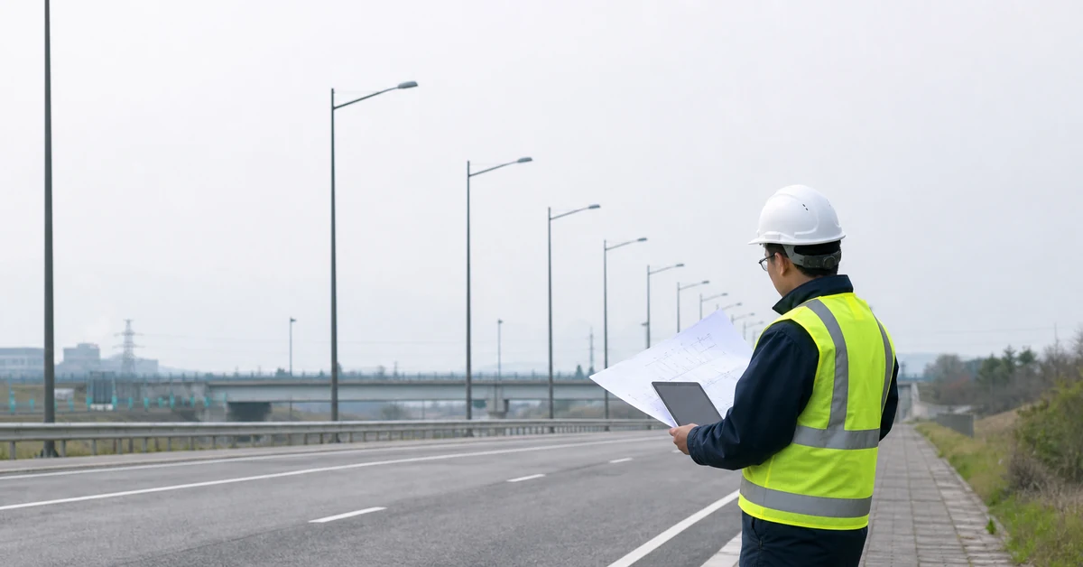
For EPC contractors, municipal teams, consultants, and tender buyers, the safe workflow is simple: use the ratio to start the comparison, then use photometric calculation and project review to select the layout.
Define Pole Height, Mounting Height, and Spacing
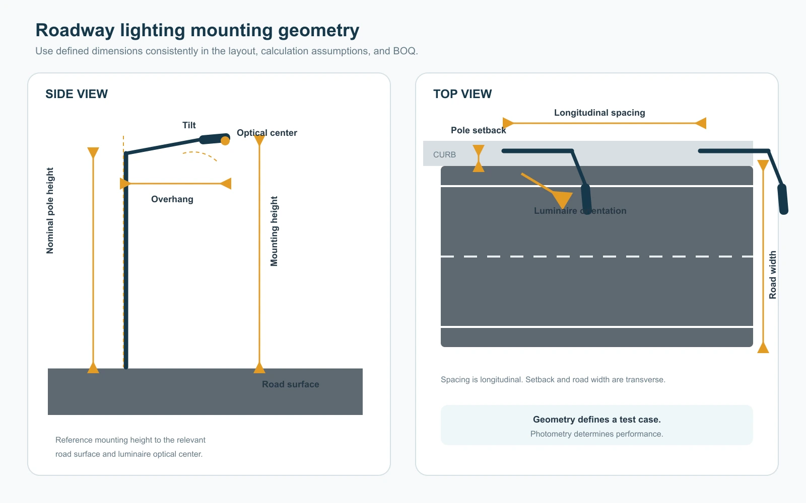
Define every dimension consistently. A calculation becomes unreliable when nominal pole height replaces mounting height or when a staggered layout uses two meanings of “spacing.†Put the definitions on the layout, calculation assumptions, and BOQ clarification.
Nominal pole height
Nominal pole height is the specified pole length or above-ground height, depending on the project convention. Embedment, foundation level, or bracket geometry may make it different from the luminaire's optical-center height.
Luminaire mounting height
Mounting height is the vertical distance from the relevant road surface to the luminaire's photometric center. This is the H used in the spacing formula and lighting model. State the reference surface if levels vary.
Longitudinal pole spacing
Pole spacing is normally the longitudinal distance between consecutive installation stations in one row. Show how it is measured on curves or irregular alignments.
Setback, overhang, and tilt
Setback is the lateral pole-to-road-edge distance; overhang is the luminaire's horizontal projection over the road; tilt is its inclination. All three can change the result without changing spacing.
For a broader structural discussion of shaft size, base plate, wind exposure, and foundation coordination, use the street light pole height and dimensions guide. This article keeps the main task on preliminary spacing and lighting verification.
Required Road and Lighting Inputs
A defensible calculation needs road geometry, installation geometry, photometric data, and performance criteria. If these inputs are incomplete, the output should be labeled as an assumption-based estimate. Wattage, pole height, and road width alone are not enough to approve a roadway-lighting layout.
Road geometry
Record the inputs by road section, because one project may contain several different calculation zones:
- illuminated road length;
- carriageway width and number of lanes;
- median width and type, if applicable;
- sidewalk, cycleway, shoulder, parking lane, or service-road widths;
- curves, slopes, junctions, roundabouts, pedestrian crossings, bridges, and obstructions;
- curb line, pole setback, and any prohibited installation zones.
A “10 m road†may mean the carriageway or the full corridor. The difference can change the evaluated area, arrangement, and optics.
Lighting requirements
Confirm who selected the lighting criteria and which document controls the project:
- applicable road or area lighting class;
- maintained luminance or maintained illuminance target;
- overall and, where required, longitudinal uniformity;
- threshold increment or other glare criterion where applicable;
- surrounding-area, edge, pedestrian, conflict-area, or obtrusive-light requirements;
- maintenance factor and operating profile;
- consultant, authority, utility, or tender-specific reporting rules.
Do not convert an unspecified “target lux†into a compliance claim. Motorized routes may use luminance-based classes, while conflict or pedestrian areas may use illuminance-based criteria. Follow the applicable project basis.
Luminaire and mounting data
The model also needs the proposed product configuration:
- exact luminaire model and rated input power;
- matching IES or LDT photometric file and revision;
- optical distribution;
- mounting height, setback, overhang, tilt, and orientation;
- single-side, opposite, staggered, or twin-central arrangement;
- maintenance factor and any dimming stage used in the calculation.
An IES/LDT filename should be traceable to the proposed product, optics, wattage, and mounting condition. A file from a similar-looking luminaire is not evidence for the specified model.
Four-Step Preliminary Spacing Workflow
The four steps are to define one road section, set the mounting geometry, choose the arrangement, and compare S/H cases. The result is a simulation shortlist, not a final drawing. Keep other variables fixed while testing spacing.
Step 1: Freeze one road section
Separate the road into sections with consistent geometry and requirements. Do not force a straight road, junction, crossing, and curved approach into one repeating rule. Record each section's length, widths, users, class, and constraints.
List unknown values as assumptions—for example: “8.0 m carriageway assumed; 1.5 m setback; sidewalk width pending.†Do not present assumptions as surveyed data.
Step 2: Select a candidate mounting height
Choose a mounting height compatible with the road width, luminaire, maintenance method, and site constraints. State the assumption and flag the pole, arm, wind load, foundation, and clearances for separate structural coordination.
If the nominal pole height and photometric mounting height differ, show both. A useful note is: “8 m nominal pole; 7.8 m optical-center mounting height above carriageway.†Use 7.8 m—not 8 m—in the spacing test.
Step 3: Select and define the arrangement
Arrangement affects both photometric performance and quantity. A single-side layout uses one longitudinal row. An opposite layout places poles on both sides at the same station. A staggered layout alternates poles between sides. A twin-central layout uses one central pole station with two luminaires.
The phrase “30 m staggered spacing†is incomplete. It may mean:
- 30 m between consecutive poles along the road, alternating sides; or
- 30 m between poles on the same side, producing a 15 m interval between successive alternating poles.
That ambiguity can double the interpreted pole quantity. The drawing and BOQ must state the convention. See the street light mounting arrangements guide for arrangement-specific layout considerations.
Step 4: Create S/H test cases
Calculate preliminary spacing with:
S₀ = H × R
Where:
- Sâ‚€ = preliminary spacing in metres;
- H = luminaire mounting height in metres;
- R = selected spacing-to-height test ratio.
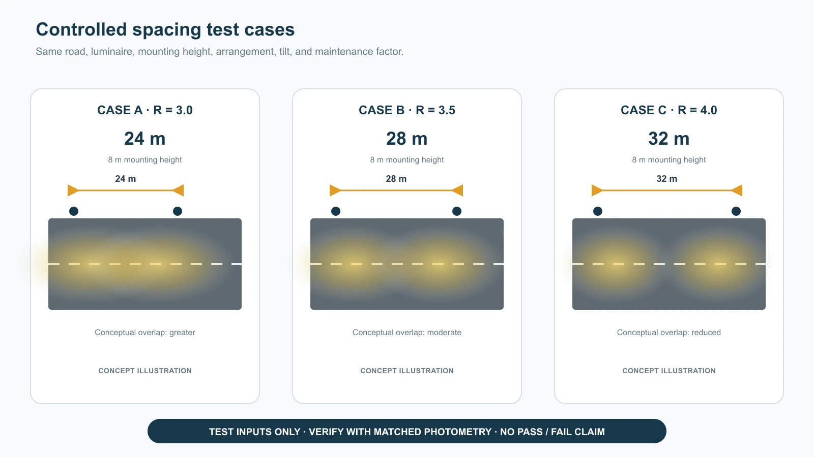
For the same road, luminaire, optics, arrangement, tilt, and maintenance factor, compare:
- Test Case A: R = 3.0;
- Test Case B: R = 3.5;
- Test Case C: R = 4.0.
These cases are not ranked as universally safe, balanced, or economical. They are comparison inputs for one road and luminaire configuration. Any case can pass or fail depending on optics, orientation, setback, road width, and required criteria.
Round Sâ‚€ only for a stated reason, such as chainage or driveway coordination. Record both calculated and proposed values and update the actual ratio.
Worked Example: 8 m Mounting Height and Poles per Kilometer
An 8 m mounting height gives 24 m, 28 m, and 32 m test spacings for R = 3.0, 3.5, and 4.0. They support controlled comparison; they do not establish a standard spacing.
Preliminary spacing
Assume:
- luminaire mounting height H = 8 m;
- straight road section;
- one repeating row for the first quantity comparison;
- no intersections, curves, crossings, or excluded pole locations.
The test cases are:
| Test case | Ratio R | Calculation | Preliminary spacing Sâ‚€ |
|---|---|---|---|
| A | 3.0 | 8 × 3.0 | 24 m |
| B | 3.5 | 8 × 3.5 | 28 m |
| C | 4.0 | 8 × 4.0 | 32 m |
Repeating density per kilometer
For a long, continuous row, approximate pole-station density with:
D ≈ 1,000 ÷ S
| Test spacing | Approximate station density | Practical reading |
|---|---|---|
| 24 m | 41.7 stations/km | about 42 repeating positions per km |
| 28 m | 35.7 stations/km | about 36 repeating positions per km |
| 32 m | 31.3 stations/km | about 31 repeating positions per km |
This density is useful for early cost comparison. It is not the exact count for a bounded one-kilometer section.
Endpoint-included count
If a separate road section of length L must have a position at both endpoints and the actual spacing must not exceed S, use:
N ≈ ⌈L ÷ S⌉ + 1
For L = 1,000 m:
| Maximum spacing | Intervals | Endpoint-included positions | Actual equalized spacing |
|---|---|---|---|
| 24 m | ⌈1,000 ÷ 24⌉ = 42 | 43 | 1,000 ÷ 42 = 23.81 m |
| 28 m | ⌈1,000 ÷ 28⌉ = 36 | 37 | 1,000 ÷ 36 = 27.78 m |
| 32 m | ⌈1,000 ÷ 32⌉ = 32 | 33 | 1,000 ÷ 32 = 31.25 m |
The difference between “about 42 positions per km†and “43 positions including both endpoints†is not an error. The first is a repeating density; the second counts two boundaries of a defined section.
Convert stations into poles and luminaires
| Arrangement | If S means station spacing | Approximate poles or pole positions per km | Approximate luminaires per km |
|---|---|---|---|
| Single-side | Distance between adjacent poles in one row | 1,000 ÷ S | Same as poles |
| Opposite | Distance between paired stations | 2 × 1,000 ÷ S | Same as poles for one luminaire per pole |
| Staggered | Distance between successive alternating poles | 1,000 ÷ S | Same as poles |
| Staggered | Distance between poles on the same side | 2 × 1,000 ÷ S | Same as poles |
| Twin-central | Distance between central pole stations | 1,000 ÷ S | 2 × pole positions for two luminaires per pole |
The final BOQ must then add or subtract positions for actual endpoints, junctions, median breaks, bridges, utility conflicts, curves, crossings, and transition zones. Never multiply a “per km†result across the entire project before checking section boundaries and arrangement definitions.
Why the Same Mounting Height Produces Different Spacing
Mounting height controls only one part of the geometry. Two 8 m installations can require different spacing because their road width, optics, mounting details, class, or maintenance assumptions differ. A catalogue table cannot replace project photometry.
Road width and evaluated zones
A wider corridor or more evaluated zones may require another arrangement, different distribution, or additional row—not simply more wattage.
Optical distribution
Optics distribute intensity across and along the road. Longitudinal reach can improve spacing yet leave weak transverse coverage. Review the Type II vs Type III roadway optics guide when selecting a candidate.
Setback and overhang
Setback changes the distance and angle to calculation points. Overhang can adjust that geometry but also affects pole loading. Model the proposed dimensions.
Tilt and orientation
Tilt can redirect intensity but may increase glare or spill. File orientation must also be correct; rotating a road optic can invalidate an otherwise plausible layout.
Maintenance factor and surface assumptions
Maintained results depend on the maintenance factor; luminance also depends on the road-surface model. Show both in the report.
Higher wattage does not automatically fix spacing
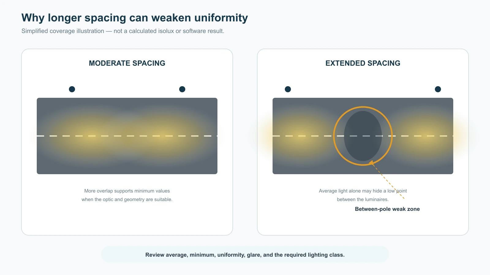
More wattage can raise average levels while leaving poor uniformity and increasing glare or energy demand. A geometry-driven dark zone may require another optic, spacing, mounting geometry, or arrangement.
When the Quick Rule Is Not Safe
Stop using S/H as the decision method when geometry is irregular, criteria are demanding, or a wrong BOQ has major consequences. Use it only to create models; let calculation and project review control selection.
Do not approve spacing from the quick rule alone when the project includes:
- high-speed or high-traffic motorized routes;
- strict luminance, overall-uniformity, longitudinal-uniformity, or glare limits;
- curves, gradients, ramps, tunnels, bridges, junctions, or roundabouts;
- pedestrian crossings, schools, hospitals, security zones, or other conflict areas;
- wide medians, service roads, cycleways, parking lanes, or multiple calculation areas;
- significant pole setback, long outreach arms, unusual tilt, or mounting obstructions;
- existing poles that force non-repeating distances;
- coastal, high-wind, flood, or difficult-maintenance conditions affecting the installation concept;
- a tender BOQ that fixes quantity before photometric review;
- a solar system where every extra watt-hour changes PV and battery sizing.
What to avoid
Do not approve a longer spacing without the road model, criteria, maintenance factor, and photometric file. A lower pole count may reflect real optimization—or omitted zones, wrong orientation, initial rather than maintained results, or untested glare.
Also avoid treating a simulation screenshot as a complete report. A colored image without inputs, result tables, file traceability, and calculation settings cannot be audited or reproduced.
What DIALux or Relux Must Verify
A simulation must verify the criteria assigned to the actual road and calculation areas, not just average lux. It needs correct geometry, file, mounting condition, maintenance assumptions, and lighting class.
Model basis
The report should identify:
- project and road-section name;
- carriageway, median, sidewalk, cycleway, shoulder, and conflict-area geometry;
- arrangement, spacing, mounting height, setback, overhang, tilt, and orientation;
- exact luminaire model, wattage, optics, and IES/LDT filename or revision;
- maintenance factor and any dimming state;
- road-surface assumption where luminance is calculated;
- selected lighting class, target criteria, and source document.
Results to review
Depending on the lighting class and project requirements, review the relevant maintained values, such as:
- average and minimum illuminance;
- average luminance;
- overall uniformity;
- longitudinal uniformity where applicable;
- threshold increment or other required glare metric;
- edge, surrounding, pedestrian, or conflict-area results where specified;
- energy indicators or operating-power assumptions where required.
The software result is not stronger than its inputs. A correct calculation with an unmatched photometric file still does not validate the proposed product.
Compare spacing as controlled scenarios
Run the 24 m, 28 m, and 32 m cases with all other inputs fixed. If one case fails, identify the failing criterion and location. Then test a controlled change—such as spacing, optics, arrangement, setback, or mounting height—rather than changing several variables at once.
DIAL describes its roadway-lighting workflow as supporting custom street profiles, luminaire arrangements, automatic adjustment of pole distance, and optimization of mounting height and tilt. The relevant official reference is the DIALux street-lighting page. For a review package, request DIALux or Relux simulation outputs together with the matching IES/LDT photometric file.
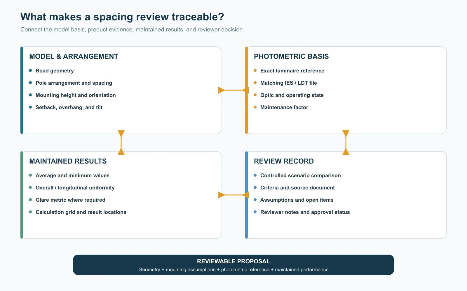
Budget Estimate vs Simulation Candidate vs Approved Layout
Every spacing value needs a status. “Budget estimate,†“simulation candidate,†and “approved layout†have different evidence levels and must not be interchangeable in quotations, tenders, or construction BOQs.
| Status | Suitable use | Minimum evidence | Must not be presented as |
|---|---|---|---|
| Budget estimate | Early quantity, cost range, option comparison | Stated road length, arrangement, mounting height, spacing convention, exclusions | Compliant lighting design |
| Simulation candidate | Photometric comparison and consultant discussion | Defined geometry, proposed product, matched IES/LDT file, criteria, calculation assumptions | Construction-approved layout |
| Approved layout | Final BOQ, coordinated drawing, procurement, installation | Accepted calculation, coordinated chainages, product and file traceability, approval record | Generic rule or supplier estimate |
Common early-BOQ problem
If a one-kilometer single-side road is priced at 32 m but matched photometry later requires 28 m, the bounded-section count changes from 33 to 37 before special zones. Those four positions also change luminaires, foundations, cable or solar systems, installation, and spares.
The problem is not that the first estimate existed. The problem is that it was allowed to become a fixed BOQ before its status changed. Keep assumptions visible and use the tender documents and BOQ review path before freezing quantities.
Solar Street Lighting Impact
For solar street lighting, spacing is both a photometric and energy-system decision. Meet the lighting requirement first, then calculate nightly energy and size the battery and PV array. Solar components cannot rescue an invalid layout.
Use this sequence:
- confirm the road sections and lighting criteria;
- select the luminaire, optics, arrangement, mounting height, and spacing candidate;
- verify maintained performance in DIALux or Relux;
- define full-power and dimming hours;
- calculate nightly energy demand in watt-hours;
- size the battery, PV array, controller, autonomy, and losses;
- recheck loading, panel orientation, shading, access, and maintenance.
Longer spacing may reduce positions but demand more output, energy, battery, PV, or pole-top capacity per position. Shorter spacing may improve uniformity but increase foundations, poles, and maintenance assets.
For that reason, compare alternatives at system level:
| Review factor | Shorter spacing may cause | Longer spacing may cause |
|---|---|---|
| Lighting | More overlap and potentially better uniformity | Larger between-pole risk and stronger dependence on optics |
| Quantity | More poles, foundations, and luminaires | Fewer installation positions |
| Energy per position | Potentially lower output per luminaire | Potentially higher output per luminaire |
| Solar hardware | More repeated systems | Larger PV/battery demand at each position may be needed |
| Structure | More poles to install | Larger luminaire or solar load may increase pole-top demand |
There is no automatic lowest-cost winner. Compare compliant configurations using the same operating hours, autonomy basis, solar resource, losses, and equipment boundaries.
Documents to Submit and Outputs to Request
A useful request separates buyer inputs from engineering outputs. Missing information should be identified before any spacing, quantity, or compliance statement is issued.
| Submit with the request | Request in the engineering output |
|---|---|
| Country, city, and project stage | Assumption and missing-information register |
| Road section lengths and dimensioned layout or CAD | Section-by-section layout and pole schedule |
| Carriageway, median, sidewalk, cycleway, and shoulder widths | Proposed mounting height, arrangement, spacing, setback, overhang, and tilt |
| Proposed pole or mounting height and any fixed pole locations | Exact luminaire model, wattage, optics, and file reference |
| Required lighting class or maintained performance criteria | DIALux/Relux report with maintained results and calculation settings |
| Arrangement and definition of spacing, if already specified | Pass/fail comparison against each required criterion |
| Existing BOQ, tender specification, and approved products list | Revised quantity basis, BOQ matching notes, and deviations |
| Solar working hours, dimming schedule, backup days, and location data | Energy basis and solar-system configuration where applicable |
| Wind, corrosion, utility, access, and authority constraints | Open issues, approval status, and next review action |
If the product model is not yet confirmed, say so. The correct output at that stage is a selection direction and missing-input list—not a model-specific compliance claim. The Engineering Support hub can route the project to photometric, simulation, drawing, or tender review.
Standards and Reference Notes
The applicable edition should follow the project tender, consultant requirement, or local authority. Where no edition is specified, the latest applicable publication should be reviewed. A standard reference sets the calculation or performance framework; it does not create a universal spacing ratio for every roadway.
- CIE 115:2010 — Lighting of Roads for Motor and Pedestrian Traffic, 2nd Edition: provides a structured model for selecting M, C, or P lighting classes.
- CIE 140:2019 — Road Lighting Calculations, 2nd Edition: addresses road-lighting calculation conventions and methods.
- ANSI/IES RP-8-25+E2 — Recommended Practice: Lighting Roadway and Parking Facilities: the current IES roadway and parking-facility recommended practice shown by IES at the time of this article's technical review.
- BS EN 13201-3:2015 — Road Lighting: Calculation of Performance: specifies calculation conventions and procedures for photometric performance. Confirm whether the tender adopts this edition or another national implementation.
- DIALux evo Street Lighting: official software capability reference for roadway profiles, arrangements, optimization, and result review.
Standards can be revised, corrected, nationally adopted, or explicitly replaced by a tender requirement. Record the title, edition, and project authority in the calculation report rather than writing only “designed to international standards.â€
FAQ
Is there a standard street light spacing-to-height ratio?
No single spacing-to-height ratio proves compliance for every road. Ratios such as 3.0, 3.5, or 4.0 can create comparison cases, but the result still depends on road width, arrangement, optics, setback, tilt, maintenance factor, and the required lighting class. Even a five-times-height proposal should be treated only as a candidate until matching photometry and a complete calculation support it.
Should spacing use pole height or luminaire mounting height?
Use the luminaire's photometric mounting height above the relevant road surface. Nominal pole height may differ because of embedment, foundation level, bracket position, or the location of the optical center. Put both dimensions on the drawing when they are not equal, and use the mounting height consistently in the ratio and DIALux/Relux model.
How do I calculate the number of street light poles per kilometer?
For a long repeating row, use D ≈ 1,000 ÷ S, where S is spacing in metres. For a separate one-kilometer section that needs a position at both ends without exceeding S, use N ≈ ⌈1,000 ÷ S⌉ + 1. Then apply the arrangement multiplier and adjust for junctions, curves, crossings, exclusions, and section transitions.
How should staggered street light spacing be counted?
First define whether spacing means the interval between successive alternating poles or the interval between poles on the same side. A 30 m same-side spacing creates approximately 15 m between consecutive alternating positions, while a 30 m consecutive-position spacing does not. State the convention on the layout and BOQ; otherwise two reviewers may calculate quantities that differ by nearly two times.
Can higher wattage allow wider pole spacing?
Sometimes it raises average light levels, but it does not automatically preserve uniformity or control glare. Wider spacing can create a dark region between poles even when the average value remains acceptable. Test the exact luminaire and optical file. A different optic, shorter spacing, revised setback, or different arrangement may be more effective than increasing power.
Can AC and solar street lights use the same spacing?
They can use the same spacing if the verified optical output and mounting geometry are equivalent, but the solar version has an additional energy constraint. Its nightly watt-hours, dimming schedule, battery, PV module, losses, autonomy, and local solar resource must support the verified lighting configuration. Do not reduce light output during required operating periods without checking the maintained-performance obligation.
What information is needed before a DIALux street-lighting review?
At minimum, provide road-section dimensions, pole or mounting height, proposed spacing, arrangement, setback, overhang, tilt, target criteria, and the exact luminaire direction. A defensible calculation also needs a matching IES/LDT file, maintenance factor, road-surface basis where relevant, special zones, and the tender or authority requirements used for acceptance.
What makes a pole-spacing layout ready for final approval?
Final approval requires more than a pass screenshot. The calculation and coordinated layout should identify the road geometry, lighting class, maintained results, arrangement, exact product and photometric file, mounting conditions, section chainages, pole schedule, BOQ, and unresolved deviations. The designated consultant, authority, or project approver—not the preliminary ratio—determines acceptance.
Submit the Layout for Pole Spacing and DIALux Review
Send the road layout, section lengths and widths, mounting height, proposed spacing, arrangement, lighting criteria, product direction, BOQ, and solar operating requirements where applicable. Sunlurio can review the calculation basis, missing inputs, IES/LDT matching path, DIALux/Relux requirements, and quantity logic before the layout is frozen.