1. Introduction
Between design intent and installation reality, most lighting engineers face a familiar challenge — how to turn thousands of simulation data points into a drawing that builders can actually follow on site.
Blueprints too often arrive after excavation has begun, or a last-minute structural update never reaches the electrical team. Each small disconnect accumulates into delay, cost, and confusion.
The Sunlurio CDD™ (Construction Design Drafting) workflow evolved from years of field coordination across multi-discipline projects where paper drawings often lagged behind design updates. It was built to close that gap — to make design intelligence move at the same speed as construction.
2. Objectives
Each objective addresses specific coordination gaps encountered in past projects — from pole alignment errors to mismatched cable trench depths. Engineers learned early that even a 50 mm offset between the civil and electrical layouts could ripple into costly rework. CDD™ was designed to eliminate that friction.
- Translate photometric and structural simulations (DIALux, HMS™, CPS™, IDS™) into buildable geometry with full coordinate traceability.
- Validate consistency among civil, electrical, and control drawings within one CAD/BIM environment.
- Standardize layering, annotation, and title-block metadata for cross-office collaboration.
- Integrate version control so every field engineer knows which drawing revision governs the work.
The intent is simple: to make drawings that engineers can trust and construction crews can interpret without hesitation.
3. Role of Construction Drawings in Lighting Projects
Construction drawings are where concept becomes action. They define not just dimensions but responsibilities.
During procurement on a Riyadh expressway project, drawing-based BOM synchronization avoided duplicate pole orders and reduced material discrepancy by roughly 8 %.
Sunlurio treats each drawing set as both a legal document and an operational manual — guiding procurement, fabrication, and installation without ambiguity.
- Design Phase: Links simulation outputs to measurable geometry.
- Procurement Phase: Ensures BOM accuracy and supplier alignment.
- Construction Phase: Serves as field authority for excavation, foundation, and wiring.
- Operation Phase: Becomes part of the digital twin for maintenance and upgrades.
4. Sunlurio CDD™ — Integrated Drafting System
In practice, each CDD™ module interacts dynamically. Engineers often switch between structural load maps and cable layouts within the same session to check coordination accuracy. The system does not merely “generate drawings” — it records the reasoning behind every dimension.
4.1 Core Modules
| Module | Function | Output |
|---|
| Site Layout | Coordinates pole spacing, cable trench, and cabinet positions; overlays survey grid. | Plan drawing (.DWG/.PDF) |
| Foundation Design | Generates reinforced concrete footing detail using HMS™ load data. | Section view (.CAD) |
| Electrical Routing | Maps conduits, junction boxes, and grounding network. | Cable schedule & single-line diagram |
| Control Integration | Positions sensors and dimming modules from IDS™ logic. | Control diagram (.SLD) |
| Revision Tracker | Logs field edits, timestamps, and engineer IDs for QA review. | Change log (.XML/.CSV) |
4.2 Workflow Overview
- Import topographic and road alignment data.
- Overlay HMS™ pole layout and optical coverage zones.
- Insert Sunlurio foundation templates (STD-Anchor series).
- Generate reinforcement sections automatically and verify clear cover.
- Connect electrical routing layers; export cable schedule.
- Review coordination visually; issue final 2D/3D BIM package.
5. Drawing Standards and Formats
Consistency across offices depends on strict but practical drafting standards.
- Sheet format: ISO A1–A3, metric scale 1:50 – 1:200.
- Layer codes: LT_ (lighting), EL_ (electrical), CV_ (civil), CT_ (control).
- Line weights: 0.13–0.50 mm per ISO 128.
- Coordinate reference: WGS 84 or local grid benchmark.
- Deliverables: .DWG/.PDF drawings, .CSV schedules, .IFC models for BIM exchange.
6. Foundation and Structural Detailing
Foundation geometry follows HMS™ simulation results but always reflects field feedback. Depth typically ranges between 2200 – 3000 mm, varying slightly with soil compaction or groundwater level. Engineers often adjust rebar cage spacing on site to match concrete vibration practices.
6.1 Foundation Types
| Type | Application | Depth (mm) | Reinforcement |
|---|
| F1 | Urban street poles ≤ 9 m | 1000–1200 (±50) | Ø12 @150 mm grid |
| F2 | Highway poles 10–12 m | 1400–1600 (±75) | Ø16 @150 mm grid |
| F3 | High-mast poles ≥ 20 m | 2200–3000 (±100) | Ø20 @100 mm + tie rings |
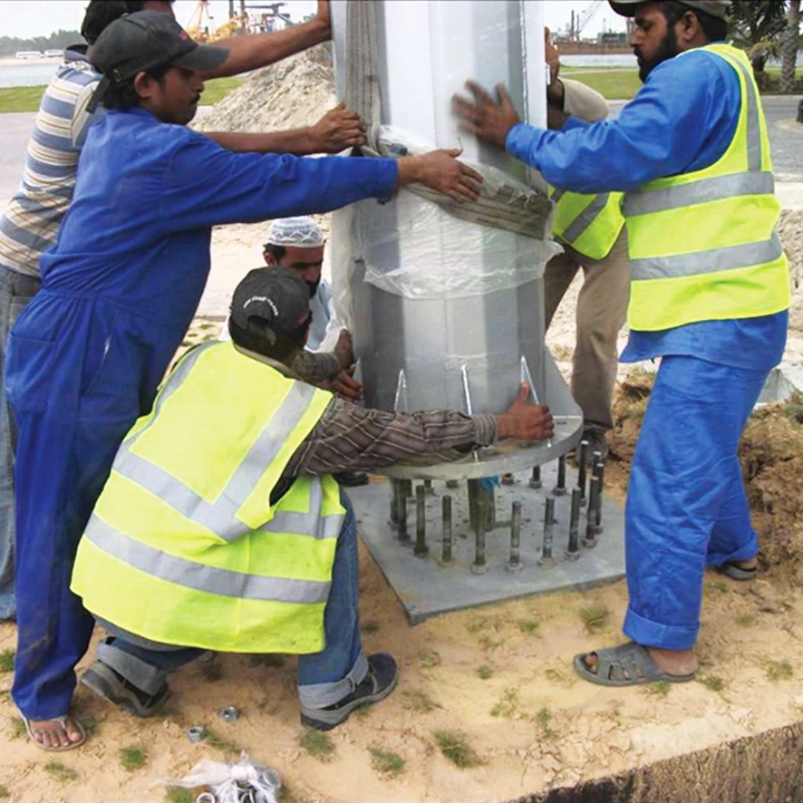
Anchor bolts (M24–M48) are positioned within ±2 mm tolerance. Drainage pipes Ø50 mm PVC prevent base-plate water accumulation — a small detail that field inspectors note often doubles pole life in humid zones.
7. Electrical and Control Schematics
Electrical drawings combine analytical precision with field adaptability. Grounding resistance readings during field testing may fluctuate ±1 Ω depending on seasonal soil moisture, so engineers note both measured and design values in the CDD™ database.
- Single-line diagrams show feeder, isolator, and branch circuits.
- Cable schedules list conductor size, insulation type, and route length.
- Grounding network: target ≤ 10 Ω per pole after installation.
- Control block diagram: links photocells, motion sensors, and gateways from IDS™ logic.
8. Drawing Coordination and Clash Prevention
Large infrastructure projects demand multidiscipline alignment. CDD™ automatically detects interferences between lighting foundations, drainage lines, and telecom ducts.
Color-coded conflict maps (red = severe, yellow = moderate) let engineers resolve issues before concrete pouring. Sometimes the simplest dimension check prevents the largest delay.
9. Field Revisions and As-Built Documentation
Site engineers frequently note that the tablet-based CDD™ viewer saves hours during inspection — a small field change no longer takes a day to circulate across teams.
When a revision is made, GPS tagging records the exact location, and a version delta (ΔV) is logged automatically. Updated drawings reach all stakeholders within 24 hours, ensuring that as-built truly equals as-installed.
10. Quality Control and Review Process
Quality control is treated as an engineering loop, not an administrative hurdle.
- Level 1 – Design Review: Authoring engineer validates geometry and loads.
- Level 2 – Peer Coordination: Independent reviewer checks cross-discipline consistency.
- Level 3 – QA Approval: Technical Division verifies Sunlurio standard compliance under ISO 9001.
Only after these three sign-offs are drawings issued to construction — engineers, not administrators, own every line they release.
11. Case Study — Urban Highway Redevelopment
During a 7 km dual-carriageway redevelopment, one recurring challenge was matching pole base coordinates with existing utility trenches.
Using CDD™, the conflict rate dropped from five per kilometer to zero — verified through on-site inspection logs.
Design-to-drawing conversion time shortened by about 38 %, and revision turnaround fell from four days to six hours.
Field verification showed a 27 % reduction in installation time due to clearer cable and foundation coordination.
12. Deliverables and Documentation
- General layout plan (.DWG / .PDF)
- Foundation and rebar detail sheets (.CAD)
- Electrical single-line diagram + cable schedule (.XLS / CSV)
- Control block diagram (IDS™ integration)
- Revision log (.XML) and as-built record (.DWG / PDF)
13. Summary
Every lighting project eventually meets the same test — can the drawings speak clearly enough to guide construction?
Accuracy and timely updates are not administrative chores; they are what stand between smooth execution and costly rework.
In the end, construction drawings are not just lines on paper — they are the shared language between design and reality. Every revision, note, and line weight carries a decision that shapes how light meets structure.
Through Sunlurio CDD™, engineers translate complex simulations into instructions that crews can build from with confidence and precision.
Author Introduction
Prepared by the Sunlurio Engineering Documentation and Drafting Division, which develops and maintains global CAD/BIM standards, drawing automation tools, and on-site revision systems for Sunlurio projects worldwide. The team’s field-driven CDD™ platform continues to evolve from direct collaboration between design engineers and construction supervisors across Africa, Southeast Asia, and the Middle East.