
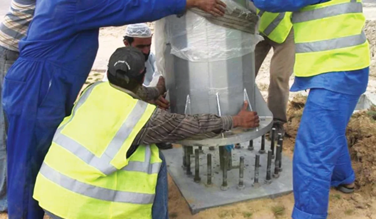
A 20 m, 25 m or 30 m high mast does not automatically come with one standard foundation size.
Before excavation, anchor-bolt fabrication or concrete work begins, the project team needs to confirm what is actually being installed above ground, what loads the mast transfers to its base, and what ground conditions the foundation must work with.
For an EPC or municipal lighting project, the practical sequence is:
High mast configuration → structural loads → site and soil conditions → foundation design → anchor-bolt and base-plate coordination → approved construction drawing.
Skipping that sequence creates one of the most expensive types of high-mast problems: civil work is completed first, but the delivered mast, base plate or anchor bolts no longer match what was cast on site.
This guide explains the information that should be confirmed before high-mast foundation construction and where the mast supplier, civil engineer and contractor need to coordinate.
1. Can You Use a Standard Foundation for a 20 m, 25 m or 30 m High Mast?
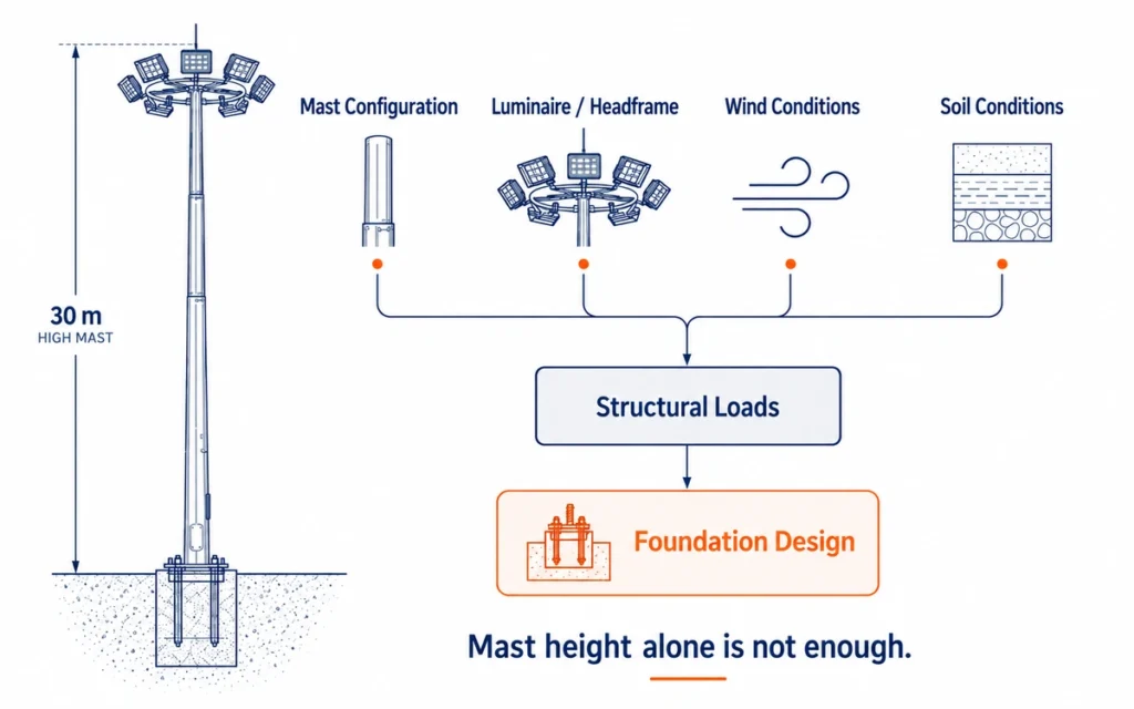
A mast height is useful project information, but height alone is not enough to determine the foundation.
Two projects can both use a 30 m high mast and still require different foundation designs.
For example:
| Design Input | Project A | Project B |
|---|---|---|
| Mast height | 30 m | 30 m |
| Luminaire arrangement | 6 luminaires | 12 luminaires |
| Installation environment | Inland site | Open or coastal site |
| Wind design basis | Project-specific | Project-specific |
| Ground conditions | Competent soil | Weaker or variable soil |
| Foundation design | Project-specific | Project-specific |
The mast height is identical, but the loading above ground and the resistance available below ground are not.
Why foundation size cannot be selected from mast height alone
The foundation has to resist the actions transferred through the mast while remaining suitable for the site conditions.
Depending on the project, relevant inputs can include:
- mast height and shaft configuration;
- mast self-weight;
- headframe or lowering-ring configuration;
- number and arrangement of luminaires;
- luminaire and equipment weight;
- projected area or other wind-loading data required by the applicable design method;
- site wind criteria;
- base reactions from the mast design;
- soil and geotechnical conditions;
- foundation type;
- base-plate and anchor-bolt arrangement.
This is why a drawing labelled “30 m High Mast Foundation” should not automatically be treated as a universal construction detail for every 30 m mast.
It may be useful as a preliminary reference, but the project team still needs to confirm that its design assumptions match the actual mast, loads, soil conditions and project requirements.
The correct question is not “What is the standard foundation size for a 30 m mast?” It is “What foundation is required for this 30 m mast at this project site?”
What can be done during tender or budgeting?
At an early tender stage, complete geotechnical information is not always available.
A preliminary foundation concept may therefore be prepared using clearly stated assumptions for budgeting, BOQ development or coordination. Those assumptions should remain visible so that they can be checked when the project moves into detailed design.
That preliminary information should not silently become the final construction basis.
Before civil construction starts, the project-specific mast configuration, structural inputs, ground conditions and required approvals should be confirmed.
2. Freeze the High Mast Configuration Before Designing the Foundation
One of the most common coordination mistakes happens when the civil foundation progresses while the high-mast package is still changing.
The project may already say “30 m high mast”, but several details can still be unresolved:
- number of luminaires;
- luminaire model;
- headframe arrangement;
- lowering-ring configuration;
- mast shaft configuration;
- electrical or mechanical accessories;
- final base plate;
- final anchor-bolt arrangement.
If those items change after the foundation design has been prepared, the structural inputs or mast-to-foundation interface may also change.
For that reason, the high mast configuration should be sufficiently defined before the foundation is released for construction.
Mast height and shaft configuration
The first step is to confirm the actual mast being supplied.
The project documentation should identify the required mast height and the configuration used for structural design. Depending on the high-mast system, this may also include shaft sections, flange connections, base-plate configuration and other structural details.
A generic description such as:
“30 m high mast pole”
is normally not enough for final civil coordination.
The civil and structural team should know which approved mast configuration the foundation information relates to.
Luminaire quantity and arrangement
The number of luminaires matters because the equipment installed at the top of the mast contributes weight and wind-exposed area.
For example:
6 × 600 W luminaires
and
12 × 800 W luminaires
describe very different lighting packages.
However, the wattage itself is primarily an electrical and lighting-performance parameter. A structural engineer also needs information relevant to physical loading, such as equipment weight, geometry, mounting arrangement and the wind-loading data required by the project design method.
Changing the luminaire arrangement after the structural package has been prepared therefore needs to be checked rather than treated as a simple lighting change.
Headframe and lowering system
A high mast is more than a steel shaft with luminaires at the top.
Depending on the system, the upper assembly can include:
- luminaire headframe;
- lowering ring;
- suspension or support components;
- electrical connections;
- cables;
- mechanical lowering equipment;
- associated accessories.
These components form part of the installed configuration and should be reflected in the information used for structural coordination.
When is the configuration sufficiently frozen?
For foundation coordination, the project team should at least know:
- the approved mast height and structural configuration;
- the luminaire quantity and arrangement;
- the relevant luminaire/equipment loading information;
- the headframe or lowering-system arrangement;
- the final base-plate configuration;
- the anchor-bolt arrangement associated with that mast.
This does not mean every minor project detail must be closed before engineering work can begin.
It means that the items capable of changing the foundation loads or mast-to-foundation interface should not still be moving when the civil contractor starts construction.
Do not freeze the foundation while the mast configuration is still changing.
3. What Structural Data Should the High Mast Supplier Provide?
Once the high mast configuration has been defined, the next question usually comes from the civil or structural engineer:
“What loads and connection information does the mast impose on the foundation?”
This is where the mast supplier and foundation designer need a clear interface.
Simply sending a generic foundation dimension is not always enough. The foundation designer needs the structural information required to evaluate the actual project conditions.
Typical supplier information may include:
| Supplier Information | Why the Project Team Needs It |
|---|---|
| Mast height and configuration | Identifies the structural system being evaluated |
| Mast and equipment weight data | Contributes to vertical loading |
| Vertical / axial load | Used in foundation structural assessment |
| Horizontal shear | Used in lateral foundation design |
| Overturning moment | Critical to foundation stability and sizing |
| Base-plate dimensions | Coordinates mast-to-foundation connection |
| Anchor-bolt arrangement | Coordinates bolt layout with civil works |
| Bolt circle / PCD | Ensures compatibility with base-plate holes |
| Luminaire and headframe configuration | Defines equipment installed at mast head |
| Wind-exposed-area data, where applicable | Supports project wind-load assessment |
The exact terminology and required load combinations depend on the structural standard, project specification and responsible engineer. The supplier's role is therefore to provide reliable mast-specific inputs, not to replace the project engineer's site-specific foundation design.
Base reactions are the key interface
A useful way to understand the relationship is:
Wind + mast + luminaires + headframe
↓
Mast structural response
↓
Base reactions
↓
Foundation design
The foundation engineer does not need only the height of the mast. They need to understand what the selected mast transfers into the foundation under the relevant design conditions.
Depending on the project, the structural interface can include:
- axial force;
- horizontal shear;
- bending or overturning moment;
- other project-specific reactions or load combinations.
Those values can then be assessed together with the geotechnical and civil design basis.
Why supplier loads and soil information must not be separated
The high-mast supplier controls information about the equipment above the foundation.
The geotechnical and civil teams control or verify the information about the ground and foundation below it.
Neither side should be working in isolation.
A typical engineering flow is:
Mast supplier data
+
Project wind criteria
+
Geotechnical information
↓
Foundation structural design
For example, the same mast reactions applied to strong competent ground and to weak or compressible soil may not result in the same foundation solution.
Likewise, good soil does not compensate for incorrect mast loads.
Both sides of the interface have to be based on the same approved project configuration.
What Sunlurio should provide for project coordination
For a project-specific high mast package, the useful discussion should therefore go beyond:
“Please send us the foundation size.”
The project team should first identify what information is required at the current stage.
For example:
Tender stage
- preliminary mast configuration;
- proposed luminaire arrangement;
- available project wind criteria;
- preliminary structural or interface information as required;
- assumptions clearly identified.
Technical submittal stage
- confirmed mast model/configuration;
- relevant structural inputs;
- base-plate information;
- anchor-bolt arrangement;
- drawing references and revisions.
Before foundation construction
- final approved mast configuration;
- coordinated base plate and anchor bolts;
- project-specific foundation design basis;
- current approved drawing revision;
- required consultant or owner approval.
This distinction prevents preliminary supplier information from being used on site as though it were already a final construction drawing.
4. How Wind Load Changes High Mast Foundation Requirements
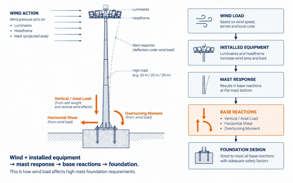
Wind is often one of the governing actions in a high mast system because the structure is tall and carries equipment at a significant height above ground.
However, a project statement such as “wind resistance: 160 km/h” does not by itself define the required foundation.
The project team still needs to establish how the specified wind conditions apply to the actual mast, luminaires, headframe and site.
Wind speed is an input, not the final foundation load
A wind-speed requirement needs to be interpreted within the design basis adopted for the project.
Depending on the applicable standard and project specification, the structural assessment may need to consider factors such as:
- the defined design wind speed;
- terrain or exposure conditions;
- mast height;
- mast geometry;
- luminaire and headframe geometry;
- wind-exposed area;
- equipment arrangement;
- applicable load combinations and safety factors.
For this reason, simply comparing two high mast quotations by the wind-speed number stated on a datasheet can be misleading.
Two manufacturers may both state the same nominal wind speed but use different mast sections, luminaire arrangements, headframes or structural assumptions.
For an EPC or consultant, the important question is whether the structural calculation and foundation inputs correspond to the actual approved project configuration.
Luminaire wattage is not wind-load data
A frequent mistake is to treat luminaire wattage as though it directly represents structural loading.
It does not.
An 800 W luminaire tells the lighting engineer something about electrical power. It does not define:
- its physical dimensions;
- its mass;
- its projected area;
- its aerodynamic characteristics;
- the number of luminaires installed;
- how those luminaires are arranged around the headframe.
A 12-luminaire high mast therefore needs to be assessed using the actual equipment configuration rather than the wattage figure alone.
Where the project design method requires effective projected area or equivalent wind-area information, that data should correspond to the proposed equipment.
Wind on the headframe also matters
The luminaires are not the only components exposed to wind.
The upper system can also include:
- headframe steelwork;
- lowering ring;
- mounting brackets;
- cables or accessories;
- other equipment specified for the project.
Their contribution should be considered where relevant to the structural model.
This becomes particularly important when a standard mast configuration is modified for a project by adding more luminaires, larger brackets or additional equipment.
How wind becomes a foundation requirement
The practical load path is:
Project wind conditions
↓
Wind acts on the mast, luminaires and headframe
↓
The mast responds structurally
↓
Loads are transferred to the mast base
↓
The foundation must resist those reactions
The foundation designer therefore works with the reactions produced by the structural system, not simply with the headline wind-speed number.
Depending on the design, these reactions can include:
- axial force;
- horizontal shear;
- overturning or bending moment.
The combination of those reactions with the ground conditions is what allows the foundation engineer to determine an appropriate foundation solution.
Why open and coastal sites need particular attention
Ports, open industrial yards, highways and coastal sites can have very different exposure conditions from sheltered urban locations.
The project engineer should therefore avoid assuming that a foundation previously used for the same mast height at another site can automatically be repeated.
A 30 m mast installed in a sheltered inland project and the same nominal mast height installed at an exposed port should still be checked against their respective project design conditions.
Same height does not mean same wind demand, and the same wind-speed label does not automatically mean the same base reactions.
5. How Soil and Geotechnical Conditions Affect the Foundation
High mast foundation design is not only an above-ground structural problem.
The mast may be identical, but the foundation can change significantly when the ground conditions change.
That is why soil information is one of the most important inputs before final foundation design.
Soil bearing capacity is only part of the picture
Safe bearing capacity or allowable bearing pressure is often the first soil value mentioned in an RFQ.
It is useful, but it should not always be treated as the only geotechnical parameter relevant to the foundation.
Depending on the foundation type and project conditions, the responsible engineer may also need information relating to:
- soil profile and layer depth;
- density or strength characteristics;
- lateral soil resistance;
- groundwater level;
- settlement potential;
- fill or reclaimed ground;
- weak layers;
- expansive or collapsible soil;
- rock level;
- slope or nearby excavation conditions.
The exact information required depends on the site and design method.
Why the same mast can need different foundations
Consider two projects using the same approved mast and the same headframe configuration.
At the first site, competent soil may provide relatively good foundation resistance.
At the second site, the upper soil layers may be weak, loose, filled or affected by groundwater.
The loads coming from the mast can be identical, but the foundation solution may not be.
The second site may require changes in:
- foundation depth;
- foundation diameter or plan dimensions;
- reinforcement;
- foundation type;
- construction method;
- ground treatment or other measures determined by the project engineer.
This is why a manufacturer should avoid presenting one standard drawing as the final answer for every project.
What if there is no soil report during tender?
This is common.
At tender or budget stage, the contractor may not yet have:
- a completed geotechnical investigation;
- borehole information for the final mast positions;
- confirmed allowable bearing parameters.
In this situation, a preliminary foundation concept may still be useful, but the assumptions need to be clearly stated.
For example:
Preliminary design basis: soil bearing capacity assumed for tender evaluation only; final foundation subject to project geotechnical data and structural approval.
That type of note is far safer than allowing an assumed value to become an invisible permanent design condition.
When should assumptions be replaced?
Before a foundation drawing is released for construction, any preliminary geotechnical assumptions that materially affect the design should be checked against the actual project information required by the responsible engineer.
This distinction is important:
Tender assumption ≠ verified site condition
and:
Reference foundation ≠ final approved foundation
The closer the project gets to excavation and concrete placement, the less acceptable it becomes to rely on undocumented assumptions.
6. How Foundation Size and Type Are Determined
Only after the mast configuration, structural loads, project wind basis and ground conditions are understood does it make sense to discuss foundation dimensions.
The foundation designer is essentially trying to create a system that safely transfers the high mast reactions into the ground while satisfying the applicable structural and geotechnical requirements.
What can change the foundation dimensions?
Depending on the project, foundation dimensions may respond to changes in:
- overturning moment;
- horizontal shear;
- axial load;
- mast height and configuration;
- headframe and luminaire arrangement;
- wind design conditions;
- soil resistance;
- groundwater;
- foundation type;
- reinforcement design;
- applicable structural criteria.
This is why two 30 m mast projects can produce different foundation diameters, depths or footing dimensions.
Common foundation concepts
Different projects may use different foundation systems.
Examples can include:
Drilled shaft or caisson foundations
A deep circular reinforced-concrete shaft may be used where this solution is appropriate for the structural loads, site and soil conditions.
Reinforced concrete spread or block foundations
A larger reinforced concrete footing or block may be suitable for some projects where space and ground conditions allow.
Pile-supported foundations
Where near-surface soil is unsuitable or project loads and geotechnical conditions require another load-transfer mechanism, a pile-supported solution may be considered by the responsible engineer.
Project-specific or rock foundations
Rock, slopes, reclaimed areas, restricted sites or unusual civil conditions may require a foundation solution specifically developed for that site.
These are not interchangeable choices selected simply by looking at mast height.
Why we do not recommend a universal “30 m high mast foundation size” table
A table saying:
20 m mast = one foundation
25 m mast = another foundation
30 m mast = another foundation
may look convenient, but it can hide the factors that actually control the project.
Such tables may be useful as preliminary internal references where all assumptions are known, but they should not be treated as a universal civil design rule.
A more reliable project process is:
- define the mast;
- define the installed equipment;
- confirm the wind design basis;
- obtain the mast reactions;
- confirm the geotechnical basis;
- design the foundation;
- coordinate the base plate and anchor bolts;
- release the approved drawing for construction.
That sequence may require more coordination at the beginning, but it reduces the risk of costly site modification later.
7. Base Plate, Anchor Bolts and PCD: Where Site Rework Often Starts
The foundation can be structurally adequate and still create a serious installation problem if the mast-to-foundation interface is wrong.
This is where the base plate, anchor bolts and PCD become critical.
Once concrete is cast, correcting these items becomes much more difficult.
Base plate
The mast base plate forms the connection between the steel mast and the foundation anchorage.
Relevant interface information can include:
- base-plate outside dimensions;
- thickness;
- number of bolt holes;
- bolt-hole diameter;
- bolt-hole position;
- plate orientation;
- relationship to the mast shaft and stiffeners where applicable.
The civil drawing and the mast fabrication drawing should refer to the same approved interface.
Anchor bolt quantity and diameter
The anchor bolts have to correspond to the base plate supplied with the mast.
The project team should therefore confirm details such as:
- quantity;
- nominal diameter;
- material or grade where specified;
- threaded length;
- projection above concrete;
- embedment arrangement;
- associated nuts and washers;
- anchor plate or cage arrangement where applicable.
Do not assume that all 25 m or 30 m high masts use the same anchor bolt specification.
What is PCD?
PCD, or pitch circle diameter, is the diameter of the circle passing through the centers of the anchor bolts.
If the base plate and foundation use different PCD values, the mast cannot simply be lowered over the bolts as intended.
For example:
Foundation anchor bolts: PCD 650 mm
but:
Delivered mast base plate: PCD 710 mm
creates a direct installation conflict.
At that point the options may involve:
- structural review;
- approved remedial work;
- base-plate modification;
- anchor modification;
- foundation rework;
- replacement components.
All of these are more difficult than confirming the correct PCD before concrete is poured.
Anchor bolt template
A template is commonly used to maintain the intended:
- bolt spacing;
- bolt-circle geometry;
- verticality;
- orientation;
- projection.
Its job is not decorative. It is a positioning control device during anchor-cage assembly and concrete work.
If the template does not match the final base plate, accurately positioning the wrong pattern still produces the wrong foundation.
Conduit and anchor cage coordination
Electrical conduits often need to pass through or enter the foundation.
Their location should be coordinated with:
- anchor bolts;
- reinforcement;
- anchor plates;
- mast access opening;
- cable route.
A conduit placed without reference to the structural and mast drawings can conflict with reinforcement or emerge in an unusable location.
The rule before concrete is poured
Do not cast the anchor cage until the final base-plate and anchor-bolt interface has been confirmed against the approved mast drawing.
This is one of the simplest checks in the entire high mast installation process, but one of the most expensive to ignore.
8. What Should a High Mast Foundation Drawing Show?
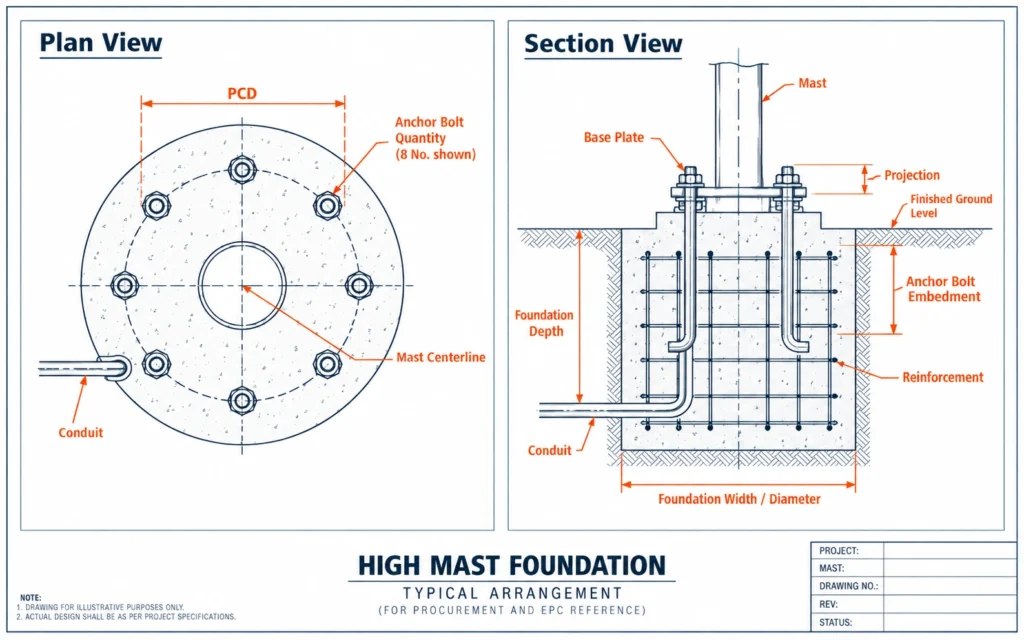
When a contractor asks for a high mast foundation drawing, the document should communicate more than the outside dimensions of a concrete block.
A usable project drawing normally needs enough information for the relevant engineering and site teams to understand the foundation geometry, reinforcement concept, mast interface and document status.
The exact content depends on the project scope and responsible designer, but the following items are commonly important.
| Drawing Information | Why It Matters |
|---|---|
| Foundation plan | Shows layout and mast center |
| Foundation section | Shows depth and vertical geometry |
| Overall dimensions | Supports excavation and concrete work |
| Finished ground level | Establishes installation reference |
| Concrete information | Supports civil construction |
| Reinforcement details | Defines structural reinforcement |
| Anchor-bolt quantity | Coordinates mast connection |
| Anchor-bolt diameter | Coordinates mast connection |
| PCD / bolt circle | Ensures base-plate compatibility |
| Bolt projection | Supports mast erection and leveling |
| Anchor embedment / cage | Defines foundation interface |
| Anchor template | Controls bolt positioning |
| Cable conduit | Coordinates electrical route |
| Grounding provision | Coordinates electrical/civil work |
| Mast / base-plate reference | Links foundation to the correct mast |
| Drawing number | Supports document control |
| Revision | Prevents use of obsolete drawings |
| Drawing status | Indicates whether the document is reference, review or construction issue |
Plan view and section view serve different purposes
The plan view is useful for understanding:
- anchor bolt arrangement;
- PCD;
- conduit location;
- mast centerline;
- overall horizontal geometry.
The section view is useful for understanding:
- foundation depth;
- concrete level;
- reinforcement;
- bolt projection;
- bolt embedment;
- conduit path;
- relationship to finished ground level.
A drawing that shows only one of these views may not provide enough information for site coordination.
Drawing revision matters as much as drawing dimensions
Consider this sequence:
Rev.0
Preliminary mast configuration
Rev.1
Luminaire arrangement changed
Rev.2
Final base plate and anchor bolts confirmed
If the civil contractor builds from Rev.0 while the supplier manufactures to Rev.2, both parties can technically be following a drawing and still end up with incompatible work.
The drawing number and revision therefore need to be controlled as part of the construction process.
9. Reference Foundation Drawing vs Approved Construction Drawing
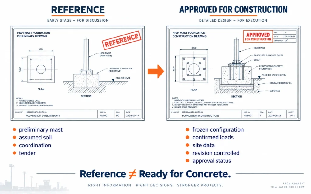
One of the most important distinctions in a high mast project is the difference between a reference drawing and a drawing that has been accepted for project construction.
These are not automatically the same document.
| Item | Reference Foundation Drawing | Project / Construction Drawing |
|---|---|---|
| Main purpose | Budgeting or early coordination | Site execution |
| Mast configuration | May be preliminary | Confirmed / approved |
| Equipment loads | May use preliminary data | Based on confirmed configuration |
| Wind basis | Reference or project assumption | Project-specific basis |
| Soil information | May be assumed | Required project basis |
| Base plate | Preliminary or reference | Coordinated with final mast |
| Anchor bolts | Preliminary or reference | Coordinated with final mast |
| Drawing revision | Preliminary | Controlled |
| Consultant / owner review | Not necessarily complete | As required by project |
| Suitable for concrete placement | Not by default | Only after required approval |
What is a reference drawing useful for?
A reference foundation drawing can still be useful during:
- tender preparation;
- civil cost estimation;
- BOQ planning;
- early coordination;
- site-space review;
- discussions with the consultant.
Its limitation should simply be clear.
A reference drawing should not be presented as though all site-specific inputs have already been verified when they have not.
When does the project need the final drawing?
Before irreversible civil work begins.
That usually means the relevant project team should have confirmed:
- final mast configuration;
- structural load basis;
- foundation design basis;
- soil/geotechnical information required for design;
- base plate;
- anchor bolts;
- PCD;
- cable interface;
- correct drawing revision;
- required technical approvals.
The exact approval process depends on the contract, project owner and jurisdiction.
Why this distinction protects both the contractor and supplier
Without this distinction, a drawing sent during quotation can reappear months later on a construction site.
The supplier may have intended it only for preliminary coordination, while the contractor may believe it is ready for construction.
Clear document status prevents that ambiguity.
A simple label such as:
FOR REFERENCE
FOR REVIEW
or
APPROVED / ISSUED FOR CONSTRUCTION
can carry significant practical meaning when combined with proper project document control.
10. Five Foundation Mistakes That Lead to Site Rework
The most serious high mast foundation problems are often not caused by a lack of technical knowledge.
They happen because information was released in the wrong sequence.

Mistake 1: Selecting the foundation only from mast height
What happens:
The project requests a “standard 30 m foundation” without confirming the actual loads or ground conditions.
Possible result:
The foundation basis does not match the installed mast or site.
Better approach:
Use mast height as one input, then confirm configuration, loads, wind basis and soil conditions.
Mistake 2: Starting civil work before the mast configuration is frozen
What happens:
The foundation is designed for one luminaire/headframe configuration, but the lighting package changes later.
Possible result:
The structural loads or base interface have to be reassessed after civil work has already progressed.
Better approach:
Freeze the project items that can change foundation loading or interface before releasing construction information.
Mistake 3: Anchor-bolt PCD does not match the base plate
What happens:
The anchor cage is fabricated from an outdated or unrelated drawing.
Possible result:
The delivered mast cannot be placed onto the foundation.
Better approach:
Cross-check the final anchor layout against the final mast base-plate drawing before concrete placement.
Mistake 4: Conduit conflicts with anchor bolts or reinforcement
What happens:
Electrical and civil details are developed separately.
Possible result:
Site cutting, rerouting or redesign is required.
Better approach:
Coordinate conduit, grounding, reinforcement and anchor cage in the foundation drawing.
Mistake 5: An obsolete revision is used on site
What happens:
The civil contractor works from an earlier revision while manufacturing proceeds from a later approved drawing.
Possible result:
The site and delivered equipment no longer match.
Better approach:
Control drawing number, revision and issue status before foundation construction.
11. Who Is Responsible for the High Mast Foundation?
One reason foundation coordination becomes confused is that several organizations are involved.
The high mast supplier, structural engineer, geotechnical engineer, EPC contractor and consultant do not necessarily have the same responsibilities.
The exact contractual responsibility always depends on the project, but a typical division may look like this:
| Party | Typical Project Role |
|---|---|
| High Mast Supplier | Provides mast configuration, relevant structural inputs and mast-to-foundation interface information |
| Structural / Civil Engineer | Designs or verifies the site-specific foundation |
| Geotechnical Engineer | Provides or verifies ground parameters |
| EPC / Civil Contractor | Coordinates drawings and executes the civil works |
| Consultant / Owner | Reviews and approves submissions where required |
| Installer | Checks site readiness and mast/foundation compatibility before erection |
What the high mast supplier should control
The supplier should be able to identify the equipment being supplied and provide accurate project information within the agreed scope.
That can include:
- mast configuration;
- mast dimensions;
- luminaire/headframe arrangement;
- structural inputs relevant to the project;
- base plate;
- anchor-bolt layout;
- PCD;
- applicable supplier drawings;
- drawing revisions.
Where Sunlurio provides a reference foundation drawing or structural package, its design assumptions and intended use should be identifiable.
What the project structural engineer should control
The responsible engineer needs to assess the project-specific conditions.
Depending on the project scope, this can include:
- applicable structural criteria;
- wind design basis;
- geotechnical information;
- foundation type;
- foundation dimensions;
- reinforcement;
- structural verification;
- local design and approval requirements.
A mast manufacturer should not silently replace this role when the contract or local regulations assign it elsewhere.
What the EPC contractor should control
The EPC or main contractor is often the party where multiple disciplines meet.
Before releasing foundation construction, the contractor should ensure that:
- supplier information is current;
- civil design uses the correct mast data;
- consultant comments are closed where required;
- anchor details match the mast;
- electrical interfaces are coordinated;
- the site team has the correct drawing revision.
This is less about performing every calculation internally and more about controlling the interfaces between project parties.
12. What to Send the Supplier Before Requesting Foundation Information
The quality of foundation information a supplier can provide depends heavily on the quality of the project inputs received.
Instead of sending only:
“Need foundation drawing for 30 m high mast.”
provide as much of the following information as is available.
| Project Information | Example |
|---|---|
| Project location | City / country |
| Application | Highway, port, airport, yard, interchange |
| Mast height | 20 m, 25 m, 30 m, etc. |
| Quantity | Number of high masts |
| Luminaire quantity | e.g. 12 luminaires per mast |
| Luminaire model | Proposed or specified model |
| Luminaire weight | Datasheet value |
| Wind-related luminaire data | As required by project design method |
| Headframe arrangement | Fixed / lowering system configuration |
| Project wind requirement | From tender or design specification |
| Applicable standard | If specified |
| Soil information | Geotechnical report or available parameters |
| Foundation responsibility | Supplier / EPC / consultant / local engineer |
| Project stage | Tender, submittal or construction |
| Required document | Loads, anchor drawing, reference foundation drawing, etc. |
| Consultant requirement | Any specific submission format or calculation requirement |
If some information is not available yet
That does not mean the discussion has to stop.
Instead, identify what is:
Confirmed
Preliminary
Assumed
Still required
For example:
Mast height confirmed at 30 m. Luminaire configuration preliminary at 12 units. Project wind requirement available. Soil report not yet issued. Foundation information required for tender budgeting only.
That is much more useful than hiding the missing information.
It allows the supplier to prepare a response appropriate to the actual project stage.
Tender stage and construction stage should not request the same document
At tender stage, the customer may need:
- preliminary foundation concept;
- approximate civil scope;
- structural interface information;
- documents to support technical evaluation.
At construction stage, the project needs much tighter control:
- confirmed mast;
- confirmed loads;
- coordinated base plate;
- coordinated anchor bolts;
- project-specific foundation basis;
- current drawing revision;
- required approvals.
Knowing the stage helps avoid both under-engineering and unnecessary work.
Before Concrete Is Poured: Final Coordination Checklist
For a practical site review, the project team should be able to answer the following questions before high mast foundation concrete is placed:
- Is the final mast height confirmed?
- Is the mast structural configuration confirmed?
- Is the luminaire quantity confirmed?
- Is the headframe or lowering system confirmed?
- Are the structural inputs based on that configuration?
- Is the project wind design basis confirmed?
- Is the required geotechnical information available?
- Has the foundation been designed or verified for the project conditions?
- Does the base plate match the approved mast?
- Do anchor bolt quantity and diameter match?
- Does the PCD match the base plate?
- Is bolt projection correct?
- Is the anchor template based on the final drawing?
- Is the conduit location coordinated?
- Is grounding coordinated?
- Is the correct drawing revision being used?
- Has the required consultant or owner approval been obtained?
If several of these answers are still “not confirmed”, concrete placement may be premature.
The cost of another drawing review before casting is usually far lower than the cost of correcting an incompatible foundation after the concrete has cured.
FAQ
Is there a standard foundation size for a 30 m high mast?
Not universally.
A 30 m mast height alone does not define the foundation. The design also depends on the mast configuration, installed equipment, project wind conditions, structural reactions and geotechnical conditions.
A reference 30 m foundation drawing may be useful for budgeting or preliminary coordination, but it should not automatically be treated as the final design for another project.
How deep should a high mast foundation be?
There is no single depth that applies to every high mast.
Foundation depth can depend on structural reactions, foundation type, soil conditions, groundwater, lateral resistance and the design method adopted by the responsible engineer.
The required depth should therefore come from the project-specific foundation design rather than from mast height alone.
What information is required for high mast foundation design?
Typical inputs can include:
- mast height and structural configuration;
- mast and equipment weights;
- luminaire/headframe configuration;
- project wind criteria;
- structural base reactions;
- base-plate details;
- anchor-bolt arrangement;
- soil/geotechnical data;
- applicable project design requirements.
The exact requirements depend on the project and responsible engineering team.
What should a high mast foundation drawing include?
Depending on project scope, a foundation drawing can include:
- plan and section views;
- foundation dimensions;
- finished ground level;
- reinforcement;
- anchor-bolt quantity and diameter;
- PCD;
- bolt projection and embedment;
- anchor template;
- conduit;
- grounding provision;
- mast/base-plate reference;
- drawing number and revision;
- document status.
A foundation drawing should also be clearly identified as reference, review or construction documentation.
Can the high mast manufacturer provide the final foundation drawing?
The answer depends on the project scope and contractual responsibility.
A high mast manufacturer can provide mast-specific structural and interface information and, where included in the supply scope, may provide reference or project foundation documentation.
However, the final site-specific civil design may still require review or approval by the project structural engineer, consultant or locally responsible professional, particularly where geotechnical conditions and local design requirements must be incorporated.
Can I use a foundation drawing from another 25 m or 30 m high mast project?
It can be used as a reference, but it should not automatically be reused for construction.
Before reuse, the project team would need to confirm that the relevant design assumptions are compatible, including:
- mast configuration;
- headframe and luminaires;
- structural reactions;
- wind design basis;
- base plate;
- anchor bolts;
- soil conditions;
- design requirements.
If those inputs differ, the foundation may also need to differ.
What happens if the anchor bolts do not match the base plate?
The mast may not be installable on the completed foundation.
Any proposed correction should be technically reviewed rather than improvised on site. Depending on the condition, remedial work may involve the foundation, anchors, base plate or replacement components.
This is why final anchor-bolt and base-plate coordination should happen before concrete placement.
What is the difference between PCD and anchor bolt diameter?
They describe different things.
Anchor bolt diameter describes the nominal size of each bolt.
PCD — pitch circle diameter — describes the diameter of the circle on which the anchor-bolt centers are positioned.
Both need to match the mast base-plate design.
Do I need a soil report for a high mast foundation?
For final site-specific design, the responsible engineer needs an adequate geotechnical basis.
At tender stage, assumed soil parameters may sometimes be used for preliminary work if they are clearly identified as assumptions.
Before construction, the project team should verify that the foundation design is based on the geotechnical information required for that project.
Planning a High Mast Project?
If your project is still at tender or technical-submittal stage, you do not need to begin by asking for a generic foundation size.
Send the available project information first:
Project location · mast height · mast quantity · luminaire configuration · wind requirement · applicable specification · soil information if available · required drawings
Sunlurio can review the high mast configuration and identify the mast, structural and foundation-interface information required for the next project stage.
For projects that have already reached civil construction, also include the current foundation drawing, base-plate drawing, anchor-bolt details and drawing revision so that the interfaces can be checked against the proposed high mast configuration.
Send High Mast Project Requirements