

Quick Answer
High mast lighting layout is not only about how far apart the poles should be.
A professional layout must also decide where each mast should be placed, which area each luminaire should cover, and how every floodlight should be aimed.
For large outdoor projects, the most common high mast lighting layout patterns include:
- Central mast layout
- Four-corner layout
- Perimeter layout
- Grid or matrix layout
- Roadway or interchange-focused layout
Each pattern has different advantages, risks, and application limits.
A logistics yard may use perimeter or grid placement. A container terminal may need pole positions coordinated with container stacks and crane lanes. A highway interchange usually requires roadway-focused pole placement and asymmetric aiming rather than a simple rectangular layout.
Before foundations are built, the layout should be verified using selected IES/LDT photometric files, aiming angles, maintained illuminance, uniformity, glare control, and DIALux or equivalent simulation.
Project Review Summary
| Item | Project Review Point |
|---|---|
| Main Topic | High mast lighting layout patterns |
| Main Decision | How to place high mast poles and aim luminaires for different project sites |
| Best-Fit Projects | Logistics yards, container terminals, ports, industrial sites, highways, interchanges, parking areas, and municipal infrastructure |
| Main Layout Patterns | Central mast, four-corner, perimeter, grid/matrix, and roadway-focused layout |
| Key Engineering Variables | Pole location, mounting height, spacing, optics, aiming angle, target zone, glare, spill light, and obstacles |
| Required Verification | IES/LDT-based lighting simulation and aiming review |
| Main Risk | Copying a simple layout pattern without checking site geometry, shadows, glare, and operational restrictions |
| Commercial Intent | Useful for EPC, consultants, engineers, and project owners preparing RFQ, DIALux design, or tender documentation |
Why Layout Patterns Matter in High Mast Lighting
High mast lighting is often used when a project needs wide-area illumination with fewer poles than conventional street lighting.
However, fewer poles also means each pole location becomes more important.
A poorly placed mast can create problems that are expensive to correct later, including:
- Dark zones between working areas
- Poor lighting near site boundaries
- Glare toward drivers or operators
- Weak CCTV visibility
- Unbalanced illumination around loading areas
- Conflict with truck routes or crane lanes
- Difficulty during maintenance
- Foundation locations that interfere with future expansion
This is why high mast layout should not begin with a random pole count.
A better process is:
- Identify the lighting area.
- Divide the site into functional zones.
- Select a suitable layout pattern.
- Review practical pole locations.
- Assign luminaires to target zones.
- Prepare an aiming schedule.
- Verify the result with photometric simulation.
If your project is still estimating the distance between poles, review the High Mast Pole Spacing Guide first. If you need a complete design workflow including DIALux, IES files, glare, and BOQ documentation, refer to the High Mast Lighting Design Guide.
This article focuses specifically on layout patterns, pole placement, and aiming examples.
Five Common High Mast Lighting Layout Patterns
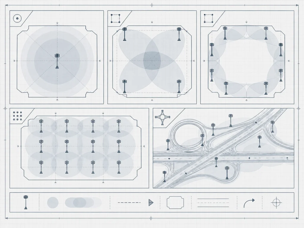
There is no single layout pattern that fits every high mast lighting project.
The correct pattern depends on:
- Project shape
- Pole installation restrictions
- Main working areas
- Traffic direction
- Required lux level
- Uniformity requirement
- Glare limitation
- Boundary spill-light control
- Obstacles and shadows
- Maintenance access
- Future site expansion
The following five patterns are commonly used during concept planning.
Central Mast Layout
A central mast layout places one high mast pole near the center of the lighting area.
This pattern is usually used for small or medium open areas where one mast can provide acceptable coverage.
Typical Applications
Central mast layout may be considered for:
- Small industrial yards
- Small parking areas
- Local service areas
- Temporary construction yards
- Small storage zones
- Isolated equipment yards
Main Advantages
The main advantage is simplicity.
A central mast layout can reduce:
- Pole quantity
- Foundation quantity
- Cable length
- Electrical distribution complexity
- Installation coordination
It also keeps the lighting system visually simple and easy to manage.
Main Limitations
A central layout is not suitable for every project.
Common risks include:
- Strong brightness near the mast
- Weak illumination near edges
- Poor uniformity in rectangular sites
- Glare toward surrounding roads or operators
- Limited flexibility if the site expands
- Shadow issues if buildings or equipment are nearby
A central mast layout is usually more suitable for compact open areas than long, narrow, or irregular sites.
Engineering Review Point
A central mast should not be selected only because it reduces pole quantity.
The design should verify whether the edge zones still meet the required maintained illuminance and uniformity. If edge performance is weak, a four-corner or perimeter layout may be more suitable.
Four-Corner Layout
A four-corner layout places high mast poles near the corners of a rectangular or near-rectangular area.
Each mast aims inward toward the project area.
Typical Applications
Four-corner layout may be considered for:
- Medium parking areas
- Small logistics yards
- Sports or open activity areas
- Storage yards
- Rectangular industrial zones
- Security-controlled compounds
Main Advantages
A four-corner layout can provide good coverage across a rectangular area when the site geometry is simple.
It can help:
- Keep poles outside the central working area
- Reduce obstruction to vehicles
- Improve inward beam control
- Provide better overlap than a single central mast
- Keep maintenance access near site edges
This pattern is often easy for project owners to understand because the pole locations appear clear and logical on a drawing.
Main Limitations
The four-corner layout may create problems if the site is too large or too irregular.
Common risks include:
- Weak illumination in the center if spacing is too wide
- Glare from opposite corners
- Over-bright corner zones
- Poor lighting along long edges
- Shadow areas near buildings
- Difficulty if one corner is unavailable for foundation work
If one corner cannot be used because of underground utilities, drainage, buildings, or road access, the layout may need to change significantly.
Engineering Review Point
A four-corner layout should be checked carefully for center-zone uniformity and edge-zone performance.
The aiming plan should avoid simply pointing all luminaires toward the center. Each luminaire should have a defined target zone to reduce hot spots and improve overlap.
Perimeter Layout
A perimeter layout places multiple high mast poles around the boundary of a project site.
The luminaires are typically aimed inward toward working areas, roads, storage zones, or loading areas.
Typical Applications
Perimeter layout is commonly used for:
- Logistics yards
- Industrial yards
- Large parking areas
- Warehouse outdoor areas
- Port working zones
- Security compounds
- Equipment storage yards
Main Advantages
Perimeter layout is practical because it keeps poles away from the center of the operation.
This helps reduce conflicts with:
- Truck movement
- Loading operations
- Material handling
- Storage layout
- Emergency routes
- Future internal reconfiguration
It can also simplify maintenance because poles are often accessible from site roads or boundary service lanes.
Main Limitations
Perimeter layout can create weak lighting if the site is very wide.
Potential problems include:
- Dark zones in the middle of the site
- Over-aiming to reach distant areas
- Higher glare toward internal operators
- Poor overlap between opposite sides
- Spill light beyond the site boundary
- Uneven coverage near corners
If the site is too wide for perimeter-only lighting, the design may need additional internal masts or a grid layout.
Engineering Review Point
Perimeter layout should be reviewed together with beam throw distance, aiming angle, and site width.
It is not enough to place poles around the boundary. The design must confirm whether the selected luminaires can provide maintained illuminance and uniformity across the full working area.
Grid or Matrix Layout
A grid or matrix layout places high mast poles across a large site in a repeated pattern.
This pattern is used when the area is too large for perimeter lighting alone.
Typical Applications
Grid or matrix layout may be used for:
- Large logistics parks
- Large container terminals
- Port yards
- Mining or industrial storage areas
- Large parking areas
- Airport apron or service areas
- Large municipal infrastructure zones
Main Advantages
A grid layout can improve coverage and uniformity across large open areas.
It allows the design team to:
- Divide the site into zones
- Improve overlap between masts
- Reduce excessive aiming distance
- Control dark zones
- Match lighting to internal traffic routes
- Support large-scale phased construction
This pattern is useful when the site cannot be covered effectively from the boundary alone.
Main Limitations
A grid layout introduces more coordination work.
Common concerns include:
- More foundations
- Longer cable routes
- Higher installation cost
- More maintenance points
- Potential conflict with operations
- Need for accurate civil coordination
- Complex aiming schedule
In some sites, internal poles may interfere with truck routes, container handling, cranes, aircraft movement, or future expansion.
Engineering Review Point
A grid layout should be coordinated with civil, electrical, structural, and operations teams before approval.
The lighting design may look strong in simulation, but the mast locations must also be practical for construction and long-term use.
Roadway or Interchange-Focused Layout
Roadway and interchange high mast layouts are different from yard lighting layouts.
The goal is not to illuminate a rectangle. The goal is to support driver visibility along road geometry while controlling glare.
Typical Applications
This pattern may be used for:
- Highway interchanges
- Large road junctions
- Toll areas
- Bridge approaches
- Ramp systems
- Municipal road intersections
- Industrial access roads
Main Advantages
A roadway-focused layout can reduce the need for many conventional street light poles in complex junction areas.
It can also support:
- Long-distance visibility
- Ramp transition lighting
- Reduced pole clutter
- Better visibility across wide junctions
- Centralized maintenance points
- Lighting of curved and merging lanes
Main Limitations
Roadway layouts require careful review of driver perspective.
Common risks include:
- Glare toward approaching drivers
- Poor visibility at merge points
- Dark transition zones
- Uneven lighting on curved ramps
- Spill light outside the road area
- Conflict with signs, bridges, or safety setbacks
A roadway-focused layout cannot be copied from an industrial yard layout.
Engineering Review Point
Pole placement should follow road alignment, viewing direction, traffic speed, and transition zones.
Specialized optics and asymmetric aiming may be required. The final layout should be verified using roadway-specific lighting criteria and consultant requirements.
Layout Pattern Comparison Table
| Layout Pattern | Best Used For | Main Advantage | Main Risk | Engineering Check |
|---|---|---|---|---|
| Central mast | Small open areas | Lowest pole quantity | Weak edge coverage | Check edge illuminance and glare |
| Four-corner | Rectangular sites | Clear inward coverage | Center or corner imbalance | Check overlap and uniformity |
| Perimeter | Logistics and industrial yards | Keeps poles outside working area | Weak center zones | Check beam throw and site width |
| Grid or matrix | Large open infrastructure sites | Better uniformity over large areas | More foundations and coordination | Check operational conflicts |
| Roadway-focused | Interchanges and road junctions | Follows traffic movement | Driver glare and transition risk | Check viewing direction and glare |
This comparison should be used only for concept selection.
The final layout still depends on the selected luminaire, mounting height, IES/LDT files, maintained lux requirement, uniformity metric, and actual site conditions.
How to Select Pole Locations

Selecting pole locations is a practical engineering decision.
A pole location must be both photometrically effective and physically buildable.
Before selecting mast positions, the project team should review:
- Site boundary
- Main working zones
- Traffic routes
- Turning radius
- Loading and unloading zones
- Crane or equipment movement
- Underground utilities
- Drainage routes
- Soil conditions
- Road safety setbacks
- Maintenance access
- Future expansion plans
- Restricted areas
The lighting engineer may prefer a pole location because it improves uniformity. However, that location may be rejected if it conflicts with underground cables, drainage, truck turning, crane movement, or safety clearance.
A good pole location usually meets three conditions:
- It supports the lighting target.
- It does not interfere with site operation.
- It can be constructed and maintained safely.
If any one of these conditions fails, the layout should be revised.
Pole Placement Decision Logic
The following decision logic can help during early layout review.
| Question | If Yes | If No |
|---|---|---|
| Is the site small and open? | Test central or four-corner layout | Review perimeter or grid layout |
| Is the site long and narrow? | Review linear or perimeter placement | Use zone-based layout comparison |
| Are internal poles allowed? | Grid layout may be possible | Use perimeter or edge-focused layout |
| Are there tall obstacles? | Adjust pole positions and aiming | Continue normal layout review |
| Is glare toward drivers critical? | Use roadway-focused placement and controlled optics | Review yard-style distribution |
| Is the site boundary sensitive? | Control spill light and avoid over-aiming | Wider aiming may be possible |
| Does the site have multiple functional zones? | Use zone-specific pole placement | Simpler layout may be acceptable |
This logic does not replace lighting simulation. It helps prevent unrealistic layouts before engineering work begins.
How to Read a High Mast Aiming Plan

A high mast aiming plan explains how each luminaire on each mast is directed toward the project area.
It is different from a simple pole layout drawing.
A pole layout drawing shows where the masts are located. An aiming plan shows how each luminaire contributes to the final lighting result.
A professional aiming plan may include:
- Mast number
- Luminaire number
- Mounting height
- Luminaire model
- Optic type
- Tilt angle
- Rotation or azimuth direction
- Target zone
- Aiming point
- Notes for installation
The aiming plan is important because high mast poles usually carry multiple luminaires.
For example, one mast may include 6, 8, 10, 12, or more floodlights. These luminaires should not all be aimed in the same direction. Each fixture should have a defined role in the lighting layout.
Without an aiming plan, the installed project may not match the simulation.
Common Aiming Terms
| Term | Meaning |
|---|---|
| Mast number | Identification number of each high mast pole |
| Luminaire number | Identification number of each fixture on the mast |
| Tilt angle | Vertical aiming angle of the luminaire |
| Rotation / azimuth | Horizontal direction of the luminaire |
| Optic type | Beam distribution selected for that luminaire |
| Target zone | Area intended to be illuminated by that luminaire |
| Aiming point | Reference point used during simulation or installation |
| Spill control | Measures used to reduce light outside the target area |
The exact format may vary by project, consultant, or lighting software, but the purpose is the same: to connect each luminaire with a defined lighting task.
Sample High Mast Aiming Schedule
The following table is an illustrative example only. It is not a final engineering design.
| Mast ID | Luminaire ID | Optic Type | Tilt Direction | Target Zone | Design Purpose |
|---|---|---|---|---|---|
| HM-01 | L1 | Wide beam | Inward | Main yard zone A | General area coverage |
| HM-01 | L2 | Wide beam | Inward | Main yard zone B | Improve overlap |
| HM-01 | L3 | Medium beam | Diagonal | Loading bay edge | Strengthen task area |
| HM-01 | L4 | Controlled beam | Boundary side | Site edge | Reduce spill light |
| HM-02 | L1 | Wide beam | Inward | Truck route | Support vehicle movement |
| HM-02 | L2 | Medium beam | Cross-yard | Central overlap | Improve uniformity |
| HM-02 | L3 | Controlled beam | Boundary side | Fence line | Security visibility |
| HM-02 | L4 | Medium beam | Diagonal | Turning area | Reduce dark zone |
In a real project, the schedule should be based on selected photometric files, mounting height, calculation grid, and final pole coordinates.
For EPC or consultant-reviewed projects, this schedule should match the DIALux or Relux report.
Example 1: Logistics Yard Layout

A logistics yard usually includes vehicle circulation, loading bays, parking zones, and storage areas.
A simple symmetrical layout may not be enough because different parts of the site have different lighting needs.
Typical Layout Pattern
A logistics yard often uses:
- Perimeter layout
- Four-corner layout
- Hybrid perimeter and internal mast layout
The selection depends on site width, loading bay position, truck routes, and allowed pole locations.
Pole Placement Review
Before finalizing pole locations, the project team should check:
- Warehouse frontage
- Loading bay shadows
- Truck turning radius
- Main circulation routes
- Parking areas
- Site entrance
- Security boundary
- Maintenance access
Poles are often placed near the boundary to avoid blocking truck movement.
However, if the yard is too wide, perimeter-only placement may create weak center-zone lighting. In that case, additional internal masts or adjusted aiming may be required.
Aiming Review
Luminaires should not simply be aimed toward the center of the yard.
A better approach is to assign target zones, such as:
- Loading bay edge
- Main truck route
- Central circulation area
- Storage zone
- Site boundary
- Entrance and exit area
The aiming schedule should improve overlap while avoiding glare toward drivers entering or leaving the yard.
Main Layout Risk
The main risk in a logistics yard is assuming that one average lux value represents the whole site.
A layout may show acceptable average illuminance but still have dark zones near loading bays, corners, or truck turning areas.
Example 2: Container Terminal Layout

Container terminals require more careful layout planning because container stacks and crane operations create changing site conditions.
Typical Layout Pattern
A container terminal may use:
- Perimeter layout
- Grid or matrix layout
- Hybrid layout around container blocks
- Roadway-focused lighting along truck lanes
The best option depends on container block arrangement, crane movement, stacking height, and truck circulation.
Pole Placement Review
The project team should check:
- Container stacking height
- Crane movement area
- Truck lanes
- Storage block layout
- Maintenance access
- Restricted foundation areas
- Operator viewing direction
- Security camera locations
Internal mast placement may improve lighting, but it must not interfere with container handling equipment.
Boundary mast placement may reduce operational conflict, but it may create long throw distances and shadow zones.
Aiming Review
In container terminals, aiming should consider both horizontal and shadowed working areas.
Luminaires may need to target:
- Truck lanes
- Container block edges
- Crane operation routes
- Gate areas
- Inspection zones
- Security boundaries
Aiming should avoid direct glare toward crane operators and vehicle drivers.
Main Layout Risk
The main risk is designing the lighting model as if the terminal were empty.
In real operation, stacked containers can block light and create shadows. The layout should be reviewed under realistic stacking assumptions whenever possible.
Example 3: Highway Interchange Layout

Highway interchanges are not designed like open yards.
The layout should follow road geometry and driver viewing direction.
Typical Layout Pattern
A highway interchange may use:
- Roadway-focused mast placement
- Central island mast placement
- Ramp-focused mast placement
- Hybrid placement around junction areas
The layout is usually shaped by traffic movement rather than site boundary.
Pole Placement Review
The project team should check:
- Main road alignment
- Ramp curves
- Merge and diverge areas
- Bridge structures
- Safety setbacks
- Sign visibility
- Driver approach direction
- Transition to adjacent lighting zones
Masts should be placed where they support visibility without creating glare toward approaching drivers.
Aiming Review
Roadway aiming should be more controlled than general yard lighting.
The luminaires may need to follow:
- Lane direction
- Ramp curvature
- Junction conflict points
- Road edge zones
- Transition areas
Asymmetric optics may be more suitable than symmetrical wide-area floodlighting.
Main Layout Risk
The main risk is using a yard-style layout for a roadway project.
A roadway project requires driver-oriented visibility, glare control, and smooth lighting transitions. Area coverage alone is not enough.
Before-and-After Layout Optimization
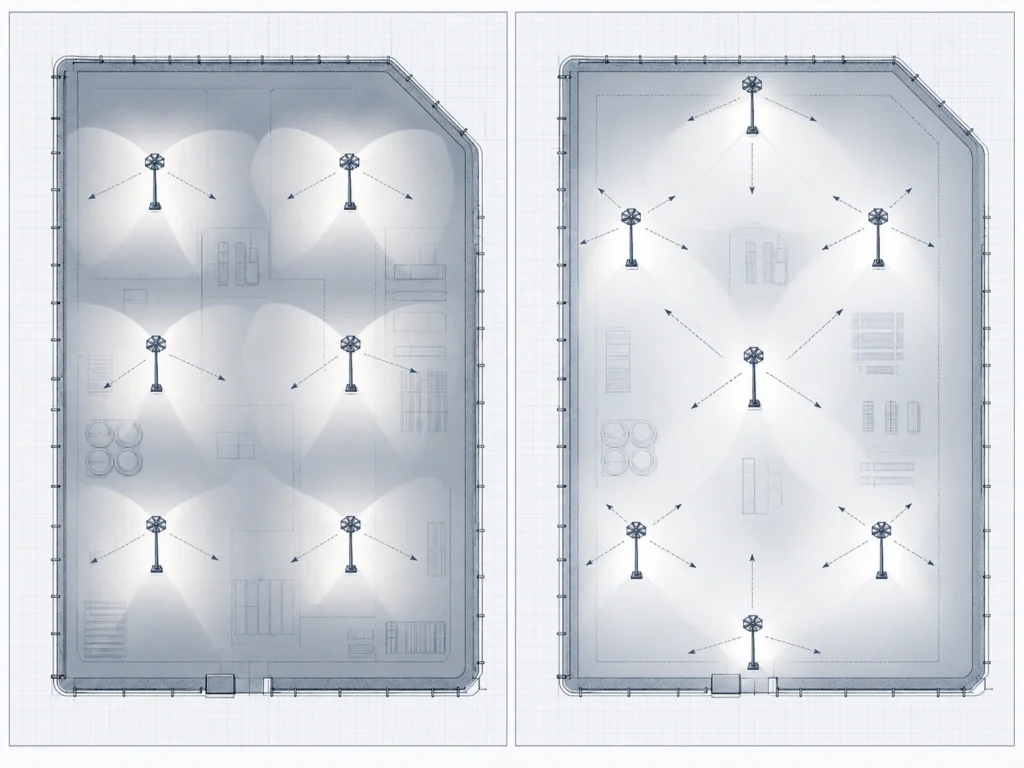
The following comparison shows how a layout may change during engineering review.
This is a conceptual example only.
| Review Item | Initial Layout | Optimized Layout |
|---|---|---|
| Pole placement | Evenly spaced around site boundary | Adjusted around loading zones and traffic routes |
| Aiming strategy | Most luminaires aimed toward site center | Luminaires assigned to specific target zones |
| Edge coverage | Weak near boundary corners | Improved through controlled aiming |
| Glare control | Some luminaires aimed toward driver approach | Aiming revised away from driver viewing direction |
| Uniformity | Dark zones between mast coverage areas | Better overlap between adjacent masts |
| Simulation status | Concept only | Verified with selected IES/LDT files |
| Installation clarity | General layout only | Mast and luminaire aiming schedule prepared |
The optimized layout may not always use fewer poles. In some cases, it uses the same pole quantity but improves luminaire aiming, target-zone assignment, and pole position.
This is why layout optimization should be completed before foundation construction.
Files Required for Layout Review
To prepare a realistic high mast lighting layout, the engineering team should receive clear project inputs.
| Required File or Input | Purpose |
|---|---|
| CAD layout or site drawing | Defines project geometry and possible pole locations |
| Site dimensions | Confirms calculation area |
| Functional zone description | Identifies roads, yards, loading zones, storage areas, and boundaries |
| Target maintained illuminance | Defines lighting performance requirement |
| Uniformity requirement | Controls dark-zone risk |
| Preferred mast height | Supports spacing and coverage review |
| Allowed pole locations | Avoids impractical foundation assumptions |
| Obstacle information | Helps review shadows and blocked light |
| Luminaire model | Defines output and optical distribution |
| IES/LDT files | Required for photometric simulation |
| Glare or spill-light limits | Supports aiming and boundary control |
| Tender or consultant specification | Defines acceptance requirements |
If these inputs are incomplete, the first layout should be treated as a concept proposal, not a final design.
For project teams preparing formal submissions, Engineering Support can help organize CAD layout review, DIALux simulation outputs, IES/LDT photometric files, and Tender Documents and BOQ Support.
Request a High Mast Layout and Aiming Review
High mast pole placement and luminaire aiming should be reviewed before foundations, cable routes, and equipment quantities are finalized.
Send us your CAD layout, target maintained illuminance, uniformity requirement, preferred mast height, allowed pole locations, site restrictions, and luminaire requirements. Sunlurio can review the layout pattern, pole placement, aiming concept, and required DIALux or IES/LDT documentation for project discussion.
Request a High Mast Layout and Aiming Review
Related High Mast Lighting Guides
The following guides explain related decisions in high mast lighting design:
- High Mast Lighting Design Guide
- High Mast Pole Spacing Guide
- How Many High Mast Lights Do You Need?
- High Mast Lighting Coverage Explained
- High Mast Lighting Systems
- Engineering Support for Lighting Projects
- DIALux Simulation Outputs
- IES/LDT Photometric Files
- Tender Documents and BOQ Support
Frequently Asked Questions
What is a high mast lighting layout pattern?
A high mast lighting layout pattern is the general arrangement of masts across a project site. Common patterns include central mast, four-corner, perimeter, grid, and roadway-focused layouts.
Which high mast layout pattern is best?
There is no single best pattern. The correct pattern depends on site geometry, lighting area, mounting height, pole restrictions, glare limits, obstacles, and the required maintained illuminance and uniformity.
What is the difference between pole spacing and layout pattern?
Pole spacing describes the distance between masts. Layout pattern describes how the masts are arranged across the site and how they relate to working zones, roads, boundaries, and obstacles.
What is the most common layout for logistics yards?
Many logistics yards use perimeter or hybrid perimeter layouts because poles can stay outside truck circulation areas. Wider yards may require internal masts or grid-style placement to improve uniformity.
What layout is suitable for container terminals?
Container terminals often require perimeter, grid, or hybrid layouts depending on container block arrangement, stacking height, crane movement, and truck lanes. The layout should account for shadows and operator glare.
How should high mast lights be aimed?
Each luminaire should be assigned a target zone. Aiming should improve coverage overlap, reduce dark zones, control glare, and avoid unnecessary spill light outside the project area.
What should be included in an aiming schedule?
An aiming schedule may include mast number, luminaire number, optic type, tilt angle, rotation or azimuth, target zone, and installation notes. It should match the lighting simulation.
Can one mast aim all luminaires in the same direction?
Usually no. High mast systems often use multiple luminaires aimed toward different zones. Aiming all luminaires in the same direction can create glare, hot spots, and poor uniformity.
Do layout patterns need DIALux verification?
Yes. Layout patterns are only concept options. The final layout should be verified using selected IES/LDT files, maintained illuminance, uniformity, glare review, and site geometry.
When should the layout be finalized?
The layout should be finalized before foundation construction, cable routing, and equipment procurement. Changing pole locations after civil work begins can be costly and time-consuming.