
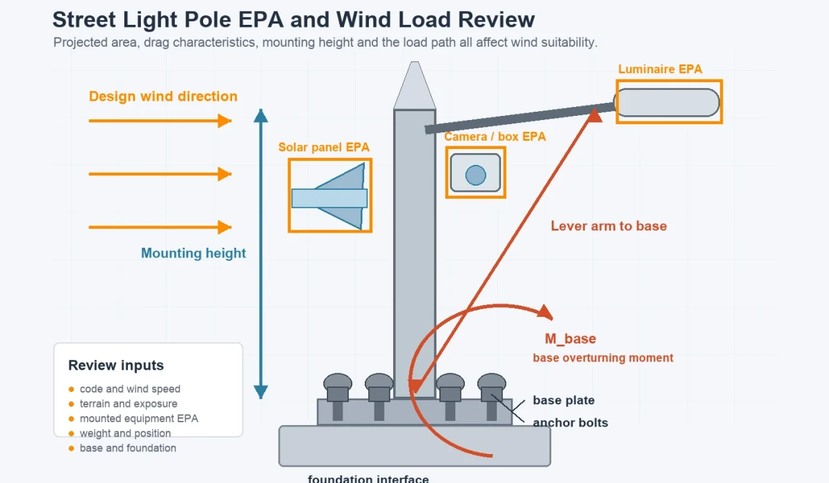
Street light pole wind resistance is the ability of the complete pole system to withstand the project’s specified wind loads without unacceptable deflection, fatigue damage, connection failure, or structural instability. For EPC teams, municipal buyers, consultants, and project engineers, this is not a catalog label. It is a design judgment that affects the pole shaft, mounted equipment, base connection, foundation, service life, and final acceptance.
Wind-related problems do not always begin with a dramatic collapse. They may first appear as excessive sway, vibration, loose anchor nuts, coating damage, long-term lean, cracked weld areas, or repeated maintenance. The risk is higher on coastal roads, open highways, bridges, ports, industrial sites, and exposed rural projects.
If your team is reviewing a road-lighting project, Sunlurio can support the preliminary selection and document-coordination process through our engineering support and datasheets and drawings pages.
Quick Answer: What Does Street Light Pole Wind Resistance Actually Mean?
Street light pole wind resistance is the ability of the complete pole system to withstand the project’s specified wind loads without unacceptable deflection, fatigue damage, connection failure, or structural instability. It cannot be judged from pole height or steel thickness alone.
A proper review must consider the applicable design code, site wind speed, terrain and exposure conditions, pole height, pole geometry, the Effective Projected Area and weight of all mounted equipment, and the capacity of the shaft, base plate, anchor bolts, and foundation.
Key Project Checks Before Pole Approval
Design Basis
Confirm the applicable code, code edition, wind-speed definition, approving authority, and required safety criteria.
Site Conditions
Confirm the project location, terrain category, exposure, altitude, topography, and coastal or corrosive conditions.
Mounted Equipment
List every luminaire, bracket, solar panel, camera, sign, communication box, banner, and other accessory that will be installed.
EPA and Weight
Confirm the Effective Projected Area and dead weight of every item mounted on the pole, including its quantity and installed position.
Pole Structure
Review the pole height, shaft shape, taper, diameter, wall thickness, material, welds, access openings, and local reinforcement details.
Base and Foundation
Check the base plate, anchor bolts, bolt circle, grout or leveling arrangement, concrete foundation, and available soil information.
Table of Contents (Tap to Expand)
- Why Wind Resistance Matters in Real Projects
- What Is EPA in Street Light Pole Design?
- What Is Wind Load for a Street Light Pole?
- What Factors Affect Street Light Pole Wind Resistance?
- How to Interpret a Wind Speed Requirement
- Which Design Standard Should Be Used?
- What Causes Street Light Poles to Fail in Wind?
- What to Avoid When Reviewing Pole Wind Resistance
- Hidden Costs of an Under-Specified Pole
- How EPC Teams and Buyers Should Review Pole Wind Suitability
- Documents to Request Before Approving a Street Light Pole
- When Does a Higher Wind-Design Requirement Matter Most?
- Need Help Reviewing a Pole Configuration?
- FAQ
Why Wind Resistance Matters in Real Projects
A lighting pole does not work in isolation. It is part of an outdoor structural system exposed to dynamic loads, vibration, corrosion, installation tolerances, and long service periods. If the design assumptions are incomplete, the resulting problem can spread from the pole shaft to the welds, base plate, anchor bolts, concrete foundation, and maintenance cycle.
In project reviews, the issue is not always “bad steel.” More often, one or two real variables were missed: a generic inland wind assumption was used for an exposed site, the final luminaire or solar panel was not included, accessories were added after approval, or the foundation was never matched to the final pole loading.
Related guidance is available in our light pole foundation design guide, lighting pole options, and coastal pole corrosion protection pages.
What Is EPA in Street Light Pole Design?
Effective Projected Area, or EPA, represents the wind-sensitive area of a luminaire or other pole-mounted component after its projected area has been adjusted by an appropriate drag coefficient.
In simplified terms:
EPA = Projected Area × Drag Coefficient
EPA is not simply the total physical surface area of the complete pole system. For pole selection, the EPA and weight of all mounted items must be identified and combined. These items may include luminaires, brackets, cameras, signs, solar panels, communication boxes, banners, and other accessories.
The combined mounted-item EPA is then reviewed against the allowable EPA capacity of the selected pole at the required pole height, design wind speed, and applicable design criteria.
Why EPA Is Important
Two poles with the same height and wall thickness may require different structural designs when their mounted equipment is different. A compact roadway luminaire creates a different wind demand from a wide solar panel, double-arm bracket, CCTV system, or communication cabinet.
A common procurement error is approving the pole first and adding accessories later. Once the mounted configuration changes, the original wind-load review may no longer be valid.
For a meaningful EPA review, confirm:
- luminaire EPA and weight;
- bracket EPA and weight;
- number of luminaires and arms;
- solar-panel dimensions and mounting angle;
- camera and communication equipment;
- signs, banners, or decorative attachments;
- mounting height and offset of each component; and
- the final combined configuration.
What Is Wind Load for a Street Light Pole?
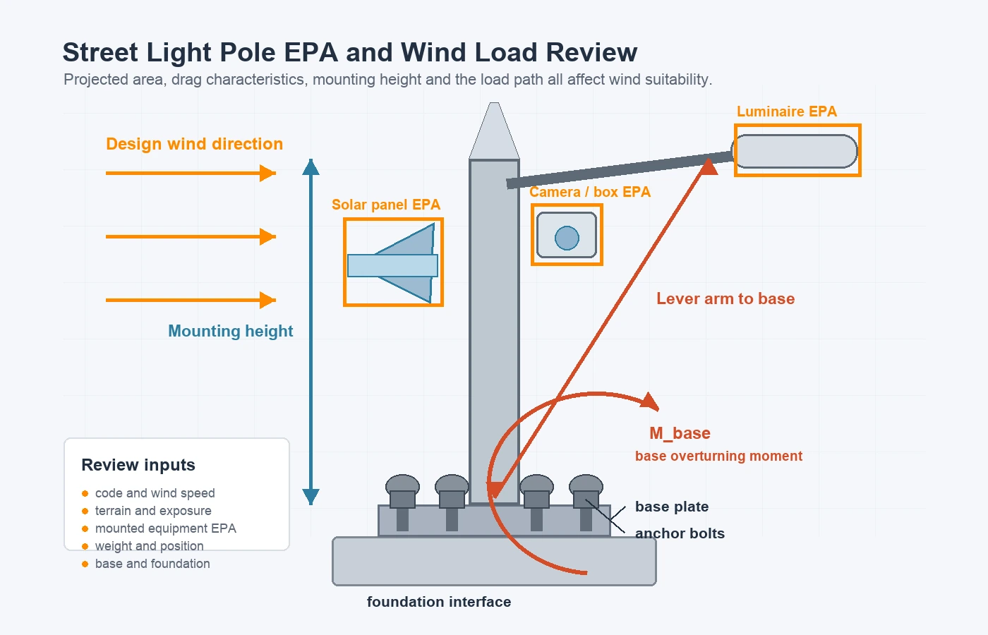
Wind load is the force created when wind pressure acts on the pole shaft and all exposed components mounted on the structure. The resulting structural demand depends not only on wind speed, but also on exposure, height, shape, drag, projected area, and the distance between each load and the pole base.
A simplified relationship is:
Wind force = Velocity pressure × Gust or response factor × Force coefficient × Projected area
Where:
- Velocity pressure depends on the design wind speed and applicable code factors.
- Gust or response factor accounts for wind fluctuations and structural response.
- Force coefficient depends on the shape and aerodynamic characteristics of the exposed component.
- Projected area is the area presented to the wind.
When EPA is already used, the projected area and drag effect have been combined. They should not be applied a second time without following the calculation method required by the selected design standard.
What Factors Affect Street Light Pole Wind Resistance?
Wind resistance is controlled by a combination of site conditions, pole geometry, mounted equipment, connections, and foundation capacity. Missing one major variable can make the entire judgment unreliable.
1. Pole Height
Taller poles generally experience higher bending moments because wind forces act through a longer lever arm. A 12-meter pole is not simply a slightly taller version of an 8-meter pole from a structural point of view. Pole height also affects the allowable mounted-equipment EPA shown in many pole-selection tables.
2. Pole Shape
Pole shape affects aerodynamic behavior and the force coefficient used in wind-load assessment. Round tapered, polygonal, octagonal, and square profiles do not interact with airflow in exactly the same way. Shape should therefore be reviewed together with the applicable calculation method rather than treated as a marketing preference.
3. Shaft Diameter and Wall Thickness
Larger shaft diameters and thicker wall sections can improve stiffness and structural resistance, but they are not independent guarantees. The required dimensions depend on wind demand, pole height, material, openings, mounting geometry, corrosion conditions, deflection criteria, and the complete load path.
4. Luminaire, Bracket, and Accessory Configuration
Wind acts on every exposed object. A double arm, long outreach bracket, wide luminaire, solar-panel frame, camera bracket, communication box, banner, or sign can materially change the total wind demand. The installed position also matters because a load farther from the base or pole centerline creates a greater moment.
Mixed-function and smart-pole projects should freeze the final accessory schedule before structural approval. See our smart street lighting system design page for wider system-planning considerations.
5. Installation Environment
A protected urban street, open coastal road, bridge, port, and mountain corridor do not impose the same wind environment even if the pole specification appears identical. Terrain, exposure, topography, altitude, local channeling effects, storm conditions, and corrosive atmosphere can all affect the design basis.
6. Foundation and Base Connection
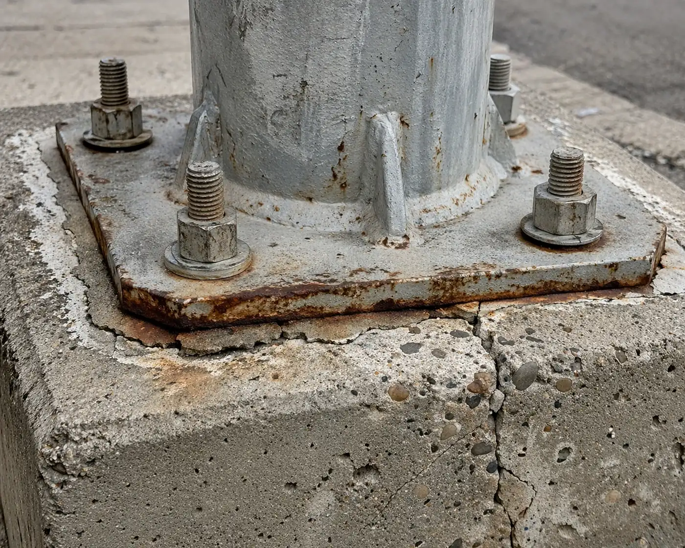
A strong pole on a weak foundation is still a weak system. Failures and maintenance problems may begin at the shaft-to-base weld, base plate, anchor bolts, grout layer, leveling arrangement, concrete interface, or surrounding soil.
The pole, base connection, and foundation should therefore be reviewed as one load path. Foundation dimensions should not be copied from another project without confirming the final pole reactions and site soil conditions. Related project-document coordination is available through our tender and BOQ support page.
7. Openings, Welds, and Local Stress
Handholes, cable-entry openings, door frames, welded brackets, and changes in shaft geometry may create local stress concentrations. These details should be included in the structural review rather than treated as minor fabrication features.
8. Fatigue and Wind-Induced Vibration
A pole may satisfy a simplified strength check and still experience long-term vibration or fatigue problems. Open terrain, steady crosswinds, long arms, flexible attachments, and certain pole geometries may require additional vibration and fatigue review.
How to Interpret a Wind Speed Requirement
A wind-speed value should not be treated as a universal pole grade. The same numerical wind speed may produce different design requirements under different codes, wind maps, averaging periods, exposure assumptions, and safety formats.
Before using a wind-speed requirement, the project team should confirm:
- the applicable design code and edition;
- whether the value is a basic, nominal, service-level, or ultimate design wind speed;
- the averaging period or gust definition;
- the required return period or reliability level;
- the terrain or exposure category;
- topographic and altitude effects;
- the final mounted-equipment configuration; and
- whether corrosion allowance, fatigue, or vibration checks are required.
| Project Input | Why It Matters | What Buyers Should Confirm |
|---|---|---|
| Wind speed | Establishes the basic wind-pressure input | Value, unit, definition, source and map basis |
| Design code | Controls the calculation method and safety format | Code name, edition and approving authority |
| Exposure or terrain | Changes wind pressure at the pole | Urban, open terrain, coastal, elevated or mountainous |
| Pole height | Changes bending moment and allowable EPA | Final mounting height and installation level |
| Mounted equipment | Adds wind area, dead load and eccentricity | EPA, weight, quantity, dimensions and position |
| Foundation conditions | Control overturning and base resistance | Foundation scope, pole reactions and soil information |
Wind speed may be shown in m/s, km/h, or mph, but unit conversion alone does not make two code requirements equivalent. The wind-speed definition and design basis must also match.
Which Design Standard Should Be Used?
The applicable design standard depends on the project country, authority, application, and tender requirements. A pole should not be described as universally compliant without identifying the actual design basis.
Common references may include:
- AASHTO specifications for structural supports used for highway signs, luminaires, and traffic signals;
- ASCE wind-load provisions where required by the project’s building or structural design criteria;
- the EN 40 series for lighting columns in relevant European and international specifications; and
- local highway-authority, municipal, airport, or project-specific structural requirements.
The final design basis should be confirmed by the project consultant, responsible engineer, or approving authority. A supplier’s general catalog statement is not a substitute for project-specific approval.
What Causes Street Light Poles to Fail in Wind?
Street light poles rarely fail because of “wind alone.” Wind exposure usually reveals a weakness in the assumptions, detailing, fabrication, installation, corrosion protection, or foundation interface.
Incomplete EPA Assumptions
The approved drawing may not include all final accessories. Adding a solar panel, larger luminaire, second arm, camera, sign, or cabinet can invalidate the original loading review.
Incorrect Site Wind Basis
Generic inland assumptions may be applied to an open coastal, elevated, or storm-prone site. A wind-speed number may also be copied without its code edition, gust definition, or exposure category.
Foundation Mismatch
The pole shaft may be adequate while the base plate, anchor bolts, concrete block, reinforcement, or soil resistance is not matched to the actual overturning moment.
Connection and Installation Errors
Loose nuts, inadequate tightening, poor leveling, missing washers, incorrect bolt projection, damaged grout, misalignment, or field modifications can turn a theoretically adequate design into a maintenance problem.
Corrosion and Long-Term Degradation
Corrosion can reduce section thickness and weaken the connection path over time, particularly around the pole base, access opening, welds, anchor bolts, and trapped-water locations. Protection and drainage are therefore part of structural durability.
What to Avoid When Reviewing Pole Wind Resistance
Do Not Approve a Pole from Height Alone
A 10-meter pole is not automatically suitable because a similar-height pole was used elsewhere. The final result depends on the mounted equipment, wind basis, pole geometry, connections, and foundation.
Do Not Treat Wind Speed as a Universal Grade
A statement such as “150 km/h wind resistance” is incomplete if it does not identify the wind-speed definition, code, exposure, final accessories, and structural scope.
Do Not Ignore Accessories Added Later
Cameras, signs, communication boxes, solar panels, banners, and extended arms add wind area, weight, and eccentricity. The structural review should be updated when the installed configuration changes.
Do Not Approve the Pole and Foundation Separately
The shaft, welds, base plate, anchor bolts, grout or leveling detail, concrete foundation, and soil resistance form one load path.
Do Not Use a Product Catalog as Final Structural Approval
Catalog dimensions and EPA tables can support preliminary selection, but final approval must match the project’s actual design basis and mounted configuration.
Do Not Ignore Corrosion, Fatigue, or Vibration
Peak wind strength is not the only concern. Long-term corrosion, repeated cyclic loading, and wind-induced vibration can affect serviceability and fatigue performance.
Hidden Costs of an Under-Specified Pole
An under-specified pole does not always fail immediately, which is why the procurement risk is easy to underestimate. The hidden costs may appear as:
- repeated inspection and maintenance;
- anchor-bolt or grout rework;
- vibration complaints;
- early corrosion repair;
- pole replacement;
- road closures or lifting-equipment costs;
- delayed handover or failed acceptance; and
- additional engineering review after installation.
A slightly higher design margin or a more complete review at procurement stage is usually less expensive than corrective work after installation.
How EPC Teams and Buyers Should Review Pole Wind Suitability
| Review Item | Required Project Information | Main Approval Risk |
|---|---|---|
| Design basis | Code, edition and approving authority | The calculation uses the wrong standard or safety format |
| Site wind speed | Value, unit, source and wind-speed definition | Values are compared on an inconsistent basis |
| Exposure and terrain | Urban, open terrain, coastal, elevated or mountainous | Wind pressure is underestimated |
| Pole geometry | Height, taper, diameter, wall thickness and material | Shaft strength or deflection is inadequate |
| Mounted equipment | Luminaire, bracket, solar panel, camera, sign and cabinet | EPA and dead weight are incomplete |
| Component position | Mounting height and distance from the pole centerline | Bending or torsional demand is underestimated |
| Base connection | Base plate, welds, bolt circle, anchors and grout | The load path fails at the connection |
| Foundation | Dimensions, concrete, reinforcement and soil data | Overturning or soil resistance is inadequate |
| Durability | Galvanizing, coating, drainage and corrosion environment | Capacity degrades during service |
| Documents | Drawings, calculations, assumptions and revision status | Approved documents do not match final supply |
Documents to Request Before Approving a Street Light Pole
EPC teams, consultants, and project buyers should request documents that match the final pole and mounted-equipment configuration, not a generic catalog model.
Depending on project stage and engineering scope, the review package may include:
- pole general arrangement drawing;
- shaft dimensions and material specification;
- luminaire and bracket dimensions;
- EPA and weight schedule for mounted equipment;
- design wind-speed basis and applicable code;
- structural calculation or loading summary where required;
- base plate and anchor-bolt drawing;
- weld, handhole, and local reinforcement details;
- foundation interface loads;
- foundation drawing where included in the supplier’s scope;
- galvanizing or coating specification; and
- document revision and model-matching record.
IES/LDT files and DIALux reports may support the lighting-performance review, but they do not replace pole structural calculations, anchor-bolt checks, or foundation design.
Document availability depends on the project stage, product configuration, engineering scope, and confidentiality requirements. Final structural approval remains subject to the applicable project authority and responsible engineer.
When Does a Higher Wind-Design Requirement Matter Most?
A more demanding or more detailed review is usually required for:
- coastal and cyclone-prone sites;
- open highways and exposed rural roads;
- bridges and elevated structures;
- ports, airports, and logistics yards;
- mountain corridors and topographically accelerated sites;
- long outreach arms or double-arm arrangements;
- solar street lights with large panels;
- smart poles carrying multiple devices;
- poles supporting signs or banners; and
- projects with long service-life or strict acceptance requirements.
These conditions do not automatically define the required pole section. They indicate that generic catalog selection is less likely to be sufficient.
Need Help Reviewing a Pole Configuration?
If your project team is reviewing a street light pole for a municipal road, highway, coastal site, solar lighting system, or smart-pole application, send the final mounting configuration and available design requirements for an initial engineering review.
Useful project inputs include:
- project country and exact location;
- applicable code or tender requirement;
- required design wind speed and unit;
- pole height and pole type;
- luminaire model, quantity, dimensions, and weight;
- bracket length and configuration;
- solar-panel dimensions and mounting angle;
- cameras, signs, cabinets, or other accessories;
- available EPA data;
- base plate and anchor-bolt requirements;
- foundation or soil information; and
- required drawings or tender documents.
Next step: Submit pole design inputs or request engineering support.
FAQ
What does EPA mean on a light pole specification?
EPA means Effective Projected Area. It represents the projected area of a luminaire or other mounted component after its wind drag has been considered. Pole selection normally uses the combined EPA and weight of all mounted items.
Can a pole be approved from wind speed alone?
No. Wind speed is only one design input. The review must also identify the design code, wind-speed definition, exposure conditions, pole height, mounted equipment, EPA, base connection, and foundation conditions.
Is a 120 km/h wind rating the same under every standard?
No. The same numerical wind speed may be defined differently under different standards. The averaging period, gust definition, return period, exposure category, and safety format must be confirmed before comparing ratings.
Do solar panels increase the wind load on a street light pole?
Yes. Solar panels may add significant projected area, dead weight, and eccentric loading. Their dimensions, mounting angle, frame, height, and orientation should be included in the pole and foundation review.
What documents should an EPC team request before pole approval?
The typical document package may include the pole drawing, material and shaft dimensions, mounted-equipment EPA and weight, design wind basis, base plate and anchor-bolt details, foundation interface loads, and structural calculations where required.
Does a DIALux report prove that a street light pole is structurally safe?
No. A DIALux report evaluates lighting performance, such as illuminance and uniformity. It does not replace wind-load calculations, pole structural verification, anchor-bolt checks, or foundation design.