
Quick Answer
There is no standard pole spacing that applies to every high mast lighting project.
During concept planning, engineers may test preliminary spacing in the range of approximately 3 to 5 times the mounting height. This is only a starting point for layout comparison, not an engineering rule or guaranteed recommendation.
The final spacing depends on the selected luminaire optics, IES/LDT photometric files, maintained illuminance target, required uniformity, glare limitation, spill-light control, site geometry, maintenance factor, structural constraints, and project specifications.
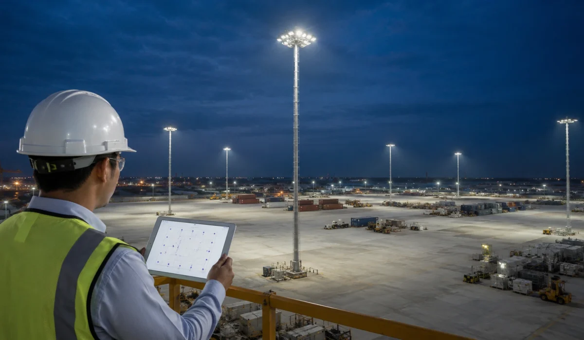
For ports, airports, logistics parks, industrial facilities, parking areas, highway interchanges, and municipal infrastructure, pole spacing should be verified through lighting calculations and DIALux or equivalent simulation before procurement or construction.
Project Review Summary
| Item | Project Review Point |
|---|---|
| Main Topic | High mast pole spacing |
| Main Decision | Determine the appropriate distance between adjacent high mast poles |
| Best-Fit Projects | Ports, airports, logistics yards, industrial facilities, parking areas, highway interchanges, and municipal infrastructure |
| Concept Planning Method | Preliminary comparison using approximately 3–5 mounting heights |
| Final Verification | DIALux or equivalent lighting simulation using the selected IES/LDT files |
| Primary Engineering Inputs | Pole height, optics, maintained illuminance, uniformity, site geometry, maintenance factor, and structural coordination |
| Main Risk | Using a fixed spacing without verifying lighting performance or project-specific constraints |
Why There Is No Standard High Mast Pole Spacing
One of the first questions asked during the planning stage of a high mast lighting project is:
How far apart should the poles be installed?
The question sounds simple, but there is no universal answer.
Unlike conventional street lighting, high mast lighting is designed for large outdoor areas where lighting performance depends on multiple engineering variables rather than one fixed distance.
Pole spacing affects:
- Number of masts.
- Foundation quantity.
- Underground cable length.
- Electrical distribution cost.
- Maintained illuminance.
- Lighting uniformity.
- Glare.
- Spill light.
- Maintenance accessibility.
- Long-term operating cost.
For project owners, increasing pole spacing may reduce the number of masts and lower initial investment. However, excessive spacing can also create dark transition zones, poor lighting uniformity, higher glare, and consultant rejection during project review.
Placing poles too close together may improve overlap, but it can also increase foundation work, installation cost, maintenance requirements, and energy consumption.
The objective is therefore not to maximize spacing. The objective is to determine the most appropriate spacing that satisfies lighting performance while keeping construction and lifecycle cost under control.
If your project is still estimating the approximate number of high mast poles required, begin with How Many High Mast Lights Do You Need?. That guide explains how project area, mounting height, and preliminary planning assumptions influence mast quantity. Once the approximate pole quantity has been reviewed, this guide focuses on how those poles should be positioned.
Concept Planning Using Mounting Height Ratios
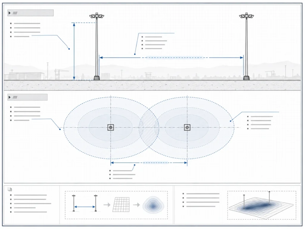
Many preliminary discussions describe high mast spacing as a multiple of mounting height.
This approach is useful during concept planning because it allows engineers to compare several layout options before detailed lighting calculations are available.
A common early-stage review may compare spacing at approximately:
- 3 × mounting height
- 4 × mounting height
- 5 × mounting height
These values should not be interpreted as engineering standards.
They are mathematical planning intervals used to test possible layouts. They help the project team understand whether a proposed mast height, pole quantity, and site layout may be reasonable before a full simulation is prepared.
The acceptable spacing must still be verified using:
- Selected luminaire photometric distribution.
- IES/LDT files.
- Maintained illuminance requirements.
- Lighting uniformity.
- Glare control.
- Spill-light restrictions.
- Actual project geometry.
- Maintenance factor.
- Owner or consultant specifications.
Some projects using specialized asymmetric optics or roadway-focused distributions may eventually justify spacing outside these preliminary intervals after simulation and engineering review. Other projects with strict uniformity, obstacles, sensitive boundaries, or high glare risk may require shorter spacing.
Preliminary Pole Spacing Matrix
The following table converts the planning ratios above into approximate concept-test intervals.
These values are mathematical planning ranges only. They are not industry averages, measured project statistics, or guaranteed application recommendations.
| Mounting Height | Concept-Test Range Only | Do Not Use Without |
|---|---|---|
| 20 m | 60–100 m | IES/LDT simulation and site geometry review |
| 25 m | 75–125 m | Maintained lux and uniformity targets |
| 30 m | 90–150 m | Optics, glare, obstruction, and aiming review |
| 35 m | 105–175 m | Structural coordination and lighting verification |
| 40 m | No generic recommendation | Project-specific engineering design |
These ranges are suitable only for:
- Early budgeting.
- Conceptual feasibility studies.
- Comparison of alternative mast heights.
- Initial layout discussion before detailed calculations.
They should not be copied directly into construction drawings or tender submissions without lighting calculation.
What Actually Determines High Mast Pole Spacing?
Pole spacing is the result of multiple engineering decisions rather than one simple calculation.
The most important variables include:
- Mounting height.
- Luminaire optics.
- Photometric distribution.
- Number of luminaires per mast.
- Aiming angles.
- Maintained illuminance target.
- Lighting uniformity.
- Glare limitation.
- Spill-light restriction.
- Maintenance factor.
- Site geometry.
- Structural coordination.
Changing any one of these variables may require the layout to be revised.
For example, two logistics parks may both specify 30 m high masts, yet require different spacing because their lighting objectives, operating conditions, obstacles, and site constraints are different.
The following sections explain how each engineering parameter influences the final spacing decision.
Pole Height Changes More Than Coverage
Pole height is often the first parameter discussed because it directly affects lighting geometry.
A higher mounting position can allow each luminaire to illuminate a wider area, but that does not automatically mean wider spacing is acceptable.
Increasing mounting height also changes:
- Viewing angles.
- Aiming requirements.
- Structural loading.
- Maintenance procedures.
- Foundation design.
- Luminaire utilization efficiency.
Depending on the selected optics and aiming strategy, a taller mast may either reduce or increase perceived glare. For this reason, mounting height should always be reviewed together with photometric distribution rather than treated as an independent spacing formula.
Higher poles also increase structural demands. Wind loading, mast stiffness, luminaire projected area, headframe configuration, and foundation design all become more significant as mounting height increases. These structural considerations do not directly determine lighting spacing, but they can limit which layout options remain practical during detailed engineering.
Luminaire Optics and IES/LDT Files Are More Important Than Wattage
Many buyers compare high mast luminaires only by wattage.
In practice, wattage alone says very little about the usable spacing between high mast poles.
Two luminaires with the same power consumption may produce completely different lighting layouts because their optics distribute light differently.
The engineering review should begin with the selected IES/LDT photometric file, which defines:
- Beam distribution.
- Intensity pattern.
- Light output at different angles.
- Utilization across the target area.
- Overlap with neighboring luminaires.
- Glare behavior.
- Spill-light direction.
A narrow distribution may project light farther but create stronger hot spots and weaker overlap. A wide distribution may improve uniformity while reducing maximum throw distance. An asymmetric distribution may be suitable for roadways, ports, or perimeter lighting, but it must be aimed correctly.
For formal design review, the selected luminaire should be evaluated using its actual IES/LDT photometric files before spacing is approved.
Maintained Illuminance Is More Important Than Initial Brightness
Another common misunderstanding is evaluating pole spacing only by how bright a lighting layout appears immediately after installation.
Professional high mast lighting projects are normally reviewed using maintained illuminance, not only initial lighting level.
Maintained illuminance considers how the lighting system will perform after months or years of operation rather than only on the commissioning day.
Several factors gradually reduce lighting performance over time:
- LED lumen depreciation.
- Luminaire dirt accumulation.
- Optical aging.
- Environmental contamination.
- Maintenance interval.
- Local dust, salt mist, or industrial pollution.
These effects are represented through the maintenance factor, which should be included in professional lighting calculation.
For this reason, increasing pole spacing based only on initial brightness can become a long-term problem. A layout that appears acceptable on the first day may no longer satisfy the required lighting level after several years of operation.
When reviewing high mast pole spacing, confirm whether the lighting report presents:
- Initial illuminance.
- Maintained illuminance.
- Maintenance factor used.
- Calculation grid.
- Calculation plane.
- Project lifetime assumptions.
The maintained lighting performance, not the initial appearance, should be the basis for engineering approval.
Lighting Uniformity Often Determines the Final Spacing
Many project owners focus on average lux because it is easy to compare between proposals.
However, professional lighting design evaluates both illuminance level and uniformity.
A project may achieve the required average illuminance while still producing unacceptable lighting conditions because of excessive variation between bright and dark areas.
Typical problems include:
- Dark transition zones between adjacent poles.
- Poorly illuminated site edges.
- Shadowed working areas.
- Inconsistent CCTV image quality.
- Reduced pedestrian visibility.
- Operator discomfort.
- Weak road-edge visibility.
For this reason, lighting reports normally include one or more uniformity metrics.
Different specifications may use different definitions, such as:
- Emin / Eavg
- Emin / Emax
- Emax / Emin
- Eavg / Emin
The project specification should state which definition is required. Avoid referring only to “uniformity ratio” without identifying the actual calculation method, because different standards and consultants may use different expressions.
In many projects, improving uniformity—not increasing average lux—is the reason spacing must be reduced or mast positions must be adjusted.
Glare and Spill Light Become More Critical as Projects Grow Larger
Pole spacing should not be evaluated only from inside the illuminated area. The surrounding environment is also important.
Increasing spacing sometimes encourages designers to use steeper aiming angles in an attempt to extend coverage. Although this may improve illuminance farther from the mast, it can also increase:
- Disability glare.
- Discomfort glare.
- Spill light beyond the project boundary.
- Unwanted light toward nearby roads.
- Light entering neighboring properties.
- Visual discomfort for drivers or operators.
Large infrastructure projects frequently require glare and spill-light control because they may be located near:
- Public roads.
- Residential developments.
- Airports.
- Ports.
- Security zones.
- Operational facilities.
- Environmental boundaries.
The relationship between mounting height and glare is not always straightforward. Increasing mounting height changes viewing angles and aiming requirements. Depending on the selected optics, luminaire orientation, and observer position, glare may either increase or decrease.
For this reason, glare should always be reviewed using the selected photometric distribution rather than assuming that taller poles automatically improve or worsen visual comfort.
Site Geometry Can Change the Entire Layout
Two projects with identical dimensions may still require completely different pole spacing because the usable lighting area is rarely a perfect rectangle.
Site geometry often introduces constraints such as:
- Buildings.
- Warehouses.
- Loading docks.
- Container stacks.
- Overhead structures.
- Underground utilities.
- Existing foundations.
- Security fences.
- Crane operating areas.
- Maintenance roads.
- Restricted pole locations.
Each obstacle influences both pole locations and luminaire aiming.
For example, a logistics yard may require open circulation areas for heavy vehicles, while a container terminal may need lighting that reaches between storage blocks without producing excessive glare toward crane operators.
Airport service areas often contain operational restrictions that prevent poles from being installed at theoretically ideal locations.
In practice, engineering layouts are usually adjusted around these constraints rather than following a perfectly regular spacing grid. Actual projects may include several different spacing distances within the same development.
Illustrative Workflow 1: Logistics Yard
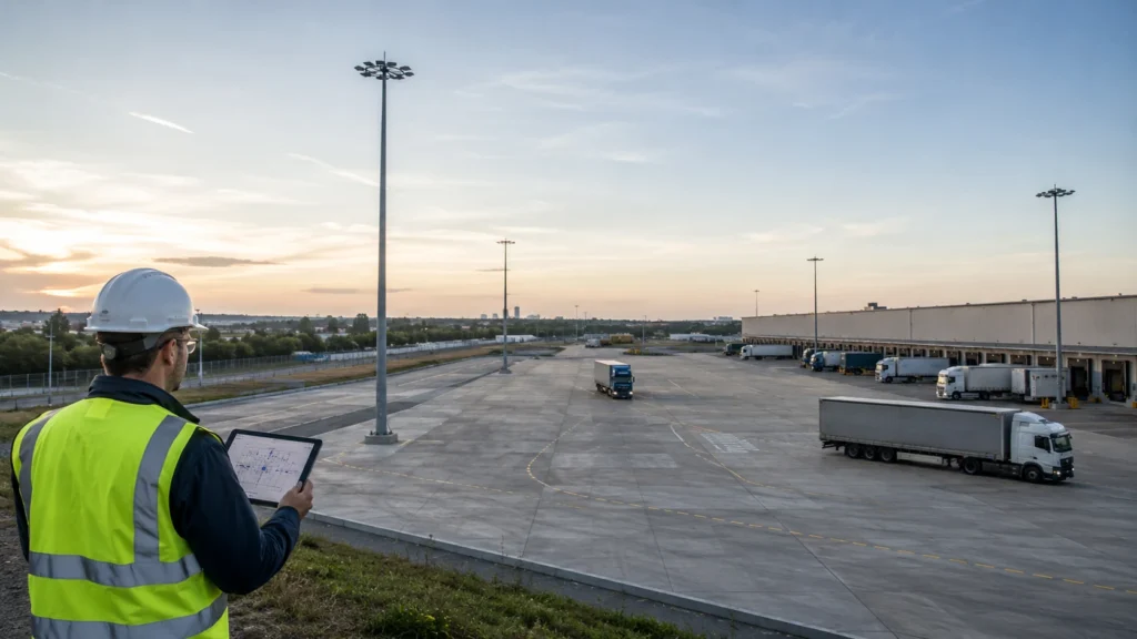
The following workflow explains the decision process only. It does not represent a completed lighting calculation.
Project Information
| Item | Example Input |
|---|---|
| Site Type | Regional logistics yard |
| Site Dimensions | 240 m × 160 m |
| Preliminary Mast Height | 25 m |
| Initial Concept Spacing | 100 m |
| Initial Layout | 6 high mast poles |
| Main Activities | Truck circulation, loading bays, storage areas |
| Design Status | Concept review before DIALux verification |
Initial Review
The concept layout appears economical because it minimizes the number of foundations.
However, several engineering questions remain unanswered:
- Are the loading bay edges sufficiently illuminated?
- Are truck turning areas visible?
- Are there dark corners near storage zones?
- Is CCTV visibility required?
- Are there buildings that block light?
- Does the layout meet maintained illuminance, not only initial lux?
- Which uniformity metric is required?
Engineering Review
After reviewing the operational layout, engineers may identify several potential weak areas:
- Loading bays near the warehouse façade.
- Circulation routes close to turning areas.
- Storage corners requiring CCTV visibility.
- Edge zones near the site boundary.
Instead of immediately increasing luminaire wattage, the engineering team should first evaluate whether adjusting pole locations can improve overlap.
One spacing interval may be reduced while maintaining the overall pole quantity. Another mast may be shifted to improve lighting at the loading bay edge.
The revised concept should then be evaluated using the selected IES/LDT file and calculation grid.
Decision Logic
The final spacing is not chosen because 100 m looks convenient. It is chosen only after the layout is checked against:
- Maintained illuminance.
- Required uniformity metric.
- Loading-zone visibility.
- Dark-zone risk.
- Glare risk.
- Maintenance access.
This workflow demonstrates that spacing decisions are rarely made by applying a fixed height ratio. They result from balancing operational requirements, lighting performance, construction cost, and long-term maintenance.
Illustrative Workflow 2: Container Terminal

Container terminals present different challenges because stacked containers, cranes, and vehicle routes create changing obstruction conditions.
Preliminary Project Information
| Item | Example Input |
|---|---|
| Application | Container storage yard |
| Proposed Mast Height | 30 m |
| Concept Spacing | 120–140 m |
| Fixture Type | High-output LED floodlights |
| Luminaire Arrangement | Multiple luminaires per mast |
| Main Risk | Shadows from stacked containers and glare toward operators |
Primary Engineering Questions
Instead of asking whether the spacing follows a height ratio, engineers should review:
- Container stacking height.
- Crane movement.
- Truck circulation.
- Working zones.
- Security camera coverage.
- Maintenance access.
- Glare toward equipment operators.
- Pole locations that do not interfere with operation.
Large container stacks may create shadowed areas that cannot be solved simply by increasing wattage.
Engineering Review
The engineering team may need to:
- Relocate individual poles.
- Adjust aiming angles.
- Select different beam distributions.
- Change luminaire quantities.
- Revise spacing locally around operational areas.
- Separate yard zones by function.
A spacing that works when the yard is empty may not work when containers are stacked.
Decision Logic
The final layout becomes a combination of lighting performance and operational efficiency rather than a mathematical spacing formula.
For container terminals, the pole spacing review should focus on usable visibility in working zones, not only theoretical coverage on an empty plan.
Illustrative Workflow 3: Highway Interchange
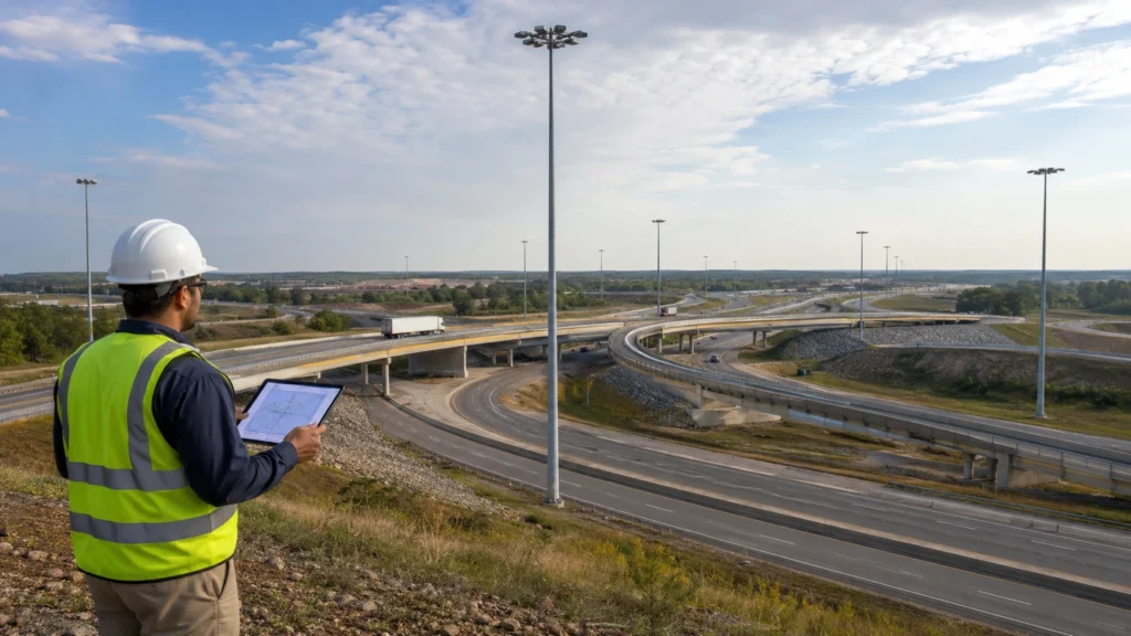
Highway interchanges are different from open industrial yards because the lighting objective is not simply to illuminate an area. The design must support driver visibility while controlling glare.
Preliminary Project Information
| Item | Example Input |
|---|---|
| Application | Highway interchange |
| Preliminary Mast Height | 35 m |
| Primary Objective | Continuous roadway visibility |
| Main Constraint | Driver glare and road geometry |
| Layout Type | Linear and curved roadway sections |
| Design Status | Concept layout before detailed simulation |
Initial Planning Review
A wider spacing may appear attractive because it reduces the number of masts and foundations.
However, roadway lighting introduces additional constraints:
- Changing road geometry.
- Entrance and exit ramps.
- Lane transitions.
- Traffic signs.
- Bridge structures.
- Driver viewing angles.
- Median or roadside locations.
Unlike an open storage yard, the lighting does not need to cover a rectangular area. It must follow the traffic path while maintaining visibility for vehicles traveling at speed.
Engineering Review
Engineers normally review:
- Roadway alignment.
- Lane configuration.
- Mounting locations.
- Luminaire aiming.
- Asymmetric beam distribution.
- Glare toward approaching drivers.
- Transition between adjacent lighting zones.
- Edge visibility.
Specialized roadway optics may allow different spacing from a conventional floodlighting layout, but the final arrangement should still be confirmed using the selected photometric files and project lighting calculations.
Decision Logic
Two projects using identical mast heights may require different spacing because their operational objectives are different.
A spacing approach suitable for a highway interchange should not be copied directly into a port, container yard, or parking area.
Engineering Inputs Required Before Pole Spacing Can Be Reviewed
One reason suppliers provide very different spacing recommendations is that the project information supplied by the client is often incomplete.
Before an engineering review begins, the following information should be collected whenever possible.
| Required Information | Why It Matters |
|---|---|
| Project application | Determines lighting objectives and operational requirements |
| Site dimensions | Defines the calculation area |
| CAD drawing or layout | Allows realistic pole positioning |
| Preferred mounting height | Influences lighting geometry |
| Permitted pole locations | Some locations may not be available due to underground services or operational restrictions |
| Target maintained illuminance | Defines performance requirements |
| Required uniformity metric | Influences overlap between adjacent poles |
| Existing obstacles | Buildings, cranes, storage areas, and trees affect lighting distribution |
| Preferred luminaire | Determines photometric distribution |
| IES/LDT file | Required for accurate simulation |
| Maintenance factor | Determines maintained lighting performance |
| Local specification or tender requirements | Defines acceptance criteria |
| Structural constraints | Coordinate mast height, headframe, wind load, and foundation feasibility |
| Boundary restrictions | Controls spill light and light trespass |
Without this information, any spacing recommendation should be treated as a preliminary planning estimate rather than a final engineering solution.
What Should Be Verified in DIALux or Relux?

A lighting simulation is far more than a visual image of the finished project.
Professional verification should confirm that the proposed spacing satisfies the required lighting performance under realistic operating conditions.
Typical review items include:
- Project dimensions.
- Pole locations.
- Mounting height.
- Luminaire model.
- IES/LDT photometric file.
- Number of luminaires per mast.
- Luminaire aiming angles.
- Maintenance factor.
- Calculation grid.
- Calculation plane height.
- Maintained average illuminance.
- Minimum illuminance.
- Maximum illuminance.
- Required uniformity metric.
- Edge lighting performance.
- Transition between adjacent poles.
- Glare review.
- Spill-light review.
- Obstacle influence.
- Boundary conditions.
For consultant-reviewed projects, these results should be documented as part of the project submission rather than treated as internal design information only.
Sunlurio can support DIALux simulation outputs and IES/LDT photometric files for high mast lighting projects when the project layout and lighting requirements are available.
Standards and Engineering References
High mast pole spacing should not be determined solely from generic online recommendations.
Project acceptance should follow applicable engineering specifications, consultant requirements, and local regulations.
Depending on project type, designers may need to consider:
- Local road lighting specifications.
- Project tender documents.
- Consultant lighting criteria.
- Airport authority requirements.
- Port authority specifications.
- Environmental spill-light restrictions.
- Roadway lighting guidelines.
- Owner acceptance requirements.
These references usually do not provide one universal spacing distance. Instead, they define the lighting performance criteria that the final design must satisfy.
For example, a roadway project may emphasize driver visibility, transition zones, and glare. An airport-related project may require authority-specific review. A port yard may focus on operational safety, equipment movement, container shadows, and security visibility.
The spacing decision should therefore be based on the project’s required lighting performance, not on a generic pole-distance table.
Common Review Mistakes
| Common Mistake | Why It Creates Risk | Better Engineering Review |
|---|---|---|
| Using only mounting height to estimate spacing | Ignores optics, target lux, uniformity, and site conditions | Review height, photometric files, maintained illuminance, and layout together |
| Treating 3–5H as a design rule | May create false confidence in early estimates | Use it only as a concept-test range |
| Selecting higher wattage instead of improving layout | More power may increase glare without improving uniformity | Review beam distribution and aiming first |
| Evaluating only average lux | Dark zones may still exist | Check minimum illuminance and the specified uniformity metric |
| Ignoring obstacles during concept planning | Buildings, containers, and equipment may block light | Include site obstructions before finalizing pole positions |
| Applying one spacing across the whole site | Different functional zones may need different lighting strategies | Divide the site by activity zone |
| Using concept spacing as construction spacing | Early ratios are not engineering approval | Verify every layout through lighting simulation before procurement |
| Comparing supplier proposals only by pole quantity | Fewer poles may not mean better value | Compare lighting performance, lifecycle cost, documentation, and maintenance |
| Ignoring glare and spill light | Can cause approval issues or user complaints | Review boundary conditions and viewing directions |
| Mixing initial and maintained values | Overstates long-term performance | Confirm maintenance factor and maintained illuminance |
Request a High Mast Pole Spacing Review
Every project has different operational requirements, lighting objectives, and site constraints.
Instead of applying a generic spacing recommendation, prepare the basic project information before requesting an engineering review.
Send us your CAD layout, target maintained illuminance, required uniformity metric, preferred mast height, allowed pole locations, and proposed luminaire information. Sunlurio can review an initial spacing concept and prepare the required IES/LDT and DIALux documentation for project discussion.
Request a High Mast Spacing Review
Related High Mast Lighting Guides
For project teams planning a complete high mast lighting project, these related guides explain the engineering decisions connected with pole spacing.
- How many high mast lights do you need?
- High mast lighting coverage explained
- High mast lighting systems
- Engineering support for lighting projects
- DIALux simulation outputs
- IES/LDT photometric files
- Tender documents and BOQ support
Frequently Asked Questions
Is there a standard spacing distance for high mast poles?
No. There is no universal spacing distance that applies to every high mast project. Pole spacing should be determined through project-specific lighting calculation, site review, and engineering verification.
Is the 3–5 mounting height ratio an engineering rule?
No. The 3–5 mounting height range is only a concept-planning method used to compare possible layouts during early design. Final spacing must be verified using photometric data, maintained illuminance, uniformity, glare review, and site geometry.
Can higher wattage increase pole spacing?
Not automatically. Higher wattage may increase light output, but spacing also depends on beam distribution, aiming angle, luminaire efficiency, uniformity requirement, and glare control.
Does a taller mast always reduce the number of poles?
Not always. A taller mast may increase coverage, but it also changes aiming, glare behavior, wind load, foundation requirements, and maintenance complexity. The final effect depends on the selected optics and site layout.
What spacing is suitable for a 30 m high mast?
For concept planning, a 30 m mast may be tested around 90–150 m spacing. This is only a preliminary range. Final spacing must be verified by lighting simulation using the selected luminaire and project requirements.
Why do different suppliers recommend different spacing?
Suppliers may use different luminaires, optics, IES/LDT files, maintenance factors, target lux values, and design assumptions. Compare complete lighting calculations rather than spacing values alone.
Can one spacing distance be used throughout an entire project?
Not always. Large sites often include different zones, such as traffic lanes, loading areas, storage zones, parking areas, and security boundaries. These zones may need different spacing or aiming strategies.
Is high mast coverage the same as pole spacing?
No. Coverage describes the area one mast can illuminate. Spacing describes how adjacent masts work together to maintain continuous lighting, overlap, and uniformity across the project area.
Do I need DIALux for high mast spacing?
For early budgeting, a rough estimate may be enough. For EPC, municipal, port, airport, industrial, or consultant-reviewed projects, DIALux, Relux, or equivalent simulation is strongly recommended.
What information should I provide for a high mast spacing proposal?
Provide site dimensions, CAD drawings, target maintained illuminance, required uniformity metric, preferred mast height, allowed pole locations, obstacles, luminaire information, and whether DIALux or tender documentation is required.
Can spacing be increased after installation?
Usually not without major cost. Once foundations and cable routes are installed, changing pole spacing becomes difficult. Spacing should be reviewed before procurement and construction.
What is the biggest mistake in high mast pole spacing?
The biggest mistake is treating spacing as a fixed distance instead of the result of a complete engineering review. A good layout should balance lighting performance, construction cost, maintenance access, glare control, and project approval requirements.