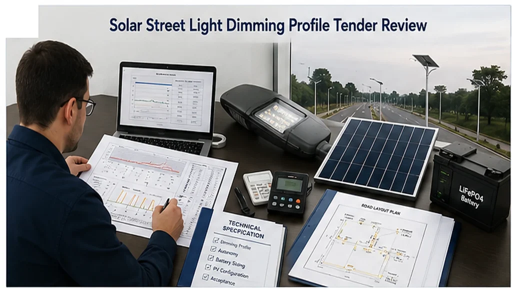
Solar Street Light Dimming Profiles for Tenders: Cost, Autonomy & Acceptance
A solar street light dimming profile for a tender should define each operating stage, its duration, output level, time reference, sensor behavior, low-battery override, and
Highway lighting design is one of the most demanding branches of outdoor illumination engineering. Unlike local roads or urban streets, highways require luminance-based design rather than simple illuminance compliance. The objective is to maintain continuous visual adaptation for high-speed drivers while minimizing glare, flicker, and energy waste. A properly simulated system ensures that each lumen contributes to the safe, efficient guidance of vehicles over long distances.
This document defines the complete design, simulation, and verification process of highway lighting systems based on EN 13201, CIE 115, and IES RP-8. It serves as a technical guideline for EPC engineers, lighting designers, and infrastructure planners developing Sunlurio smart LED highway solutions worldwide.
Good highway lighting is not about brightness, but balance — between luminance, contrast, and visual comfort. The key design target is not how much light reaches the road, but how the road surface appears to a driver moving at 80–120 km/h. Therefore, simulation must consider the driver’s eye height (1.5 m), viewing direction (1°–2° below horizontal), and the road’s reflection properties (q₀, r-tables).
The design principles are summarized as:
All professional highway lighting designs must reference at least one of the following frameworks:
These standards establish the performance indices listed below:
| Criterion | Symbol | Definition | Typical Value (ME2–ME3) |
|---|---|---|---|
| Average Luminance | Lavg | Mean road brightness seen by driver | 1.0–1.5 cd/m² |
| Overall Uniformity | U₀ | Lmin / Lavg | ≥0.4 |
| Longitudinal Uniformity | U₁ | Lmin / Lmax along travel axis | ≥0.7 |
| Threshold Increment | TI | Percentage glare-induced loss of contrast | ≤10–15% |
| Surround Ratio | SR | Lavg(surround) / Lavg(carriageway) | 0.5–0.7 |
| Upward Light Ratio | ULR | Percentage of flux above horizon | ≤1% |
At any point P on the pavement, the luminance observed from the driver’s eye position is computed as:
L(P) = Σ [ (I(θi,φi) · cos³(θi)) / (r_i²) ] × ρ(β,φr)
where:
The road surface reflection determines perceived luminance. Asphalt surfaces are classified by CIE road surface types (R1–R4):
| Surface Type | Typical Road | q₀ (cd·m⁻²·lx⁻¹) | Description |
|---|---|---|---|
| R1 | Dry asphalt | 0.07 | Specular, dark surface |
| R2 | Average asphalt | 0.10 | Medium reflection |
| R3 | Concrete | 0.12 | Light-colored pavement |
| R4 | Light concrete | 0.15 | Highly reflective |
For wet conditions, reduce q₀ by 20–40% depending on surface texture. In DIALux EVO, use the built-in “CIE Road Surface Type” parameter for accurate luminance simulation.
Geometric variables strongly affect uniformity, glare, and economic performance. The main parameters are:
| Arrangement | Description | Application |
|---|---|---|
| Single-sided | Poles on one side of the road | Urban or narrow highway, ≤2 lanes |
| Opposite | Poles on both sides aligned | Wider roads, 4–6 lanes |
| Staggered | Poles alternating sides | Most efficient for wide highways |
| Twin-central | Poles in median with dual outreach | Expressways and dual carriageways |
The first design estimate often uses the S/H ratio method:
S/H = (K × U₀ × cos³(T)) / (TI_limit)
where K is a constant derived from the luminaire’s optical class and road width. Practical values are:
Highway lighting operates typically 4200–4500 hours per year. Smart control reduces energy by 40–60% without affecting safety.
P(t) = P₀ × [Ereq(t) / Emax]^n (n ≈ 1.2–1.4)
Example: 100% output from sunset–22:00, 70% from 22:00–24:00, 50% after midnight (low-traffic period). Power control through DALI-2 scenes or Sunlurio Cloud gateway allows real-time adjustment based on vehicle flow data.
Design input: Dual carriageway, 12 m total width, R2 surface, 10 m pole height, 35 m spacing, staggered arrangement, Type III optics, 3500 K, 150 W LED.
Simulation results (DIALux EVO):
| Parameter | Result | Requirement | Status |
|---|---|---|---|
| Lavg | 1.52 cd/m² | ≥1.5 cd/m² | Pass |
| U₀ | 0.43 | ≥0.4 | Pass |
| U₁ | 0.74 | ≥0.7 | Pass |
| TI | 9% | ≤10% | Pass |
| Power density | 1.32 W/m² | — | Efficient |
Compared to a legacy 250 W HPS system, energy consumption reduced by 58%, and maintenance interval extended from 12 to 36 months.
Highway lighting simulation design is the intersection of photometry, geometry, and human factors. Every pole position, every beam angle, and every reflection coefficient must be validated against physics and driver perception. Through advanced simulation with DIALux EVO and AGi32, Sunlurio engineers transform design theory into measurable safety and energy outcomes. The result: a reliable, efficient, and environmentally responsible highway lighting network built for 24/7 performance.
Written by the Sunlurio Roadway Lighting Division. The team specializes in EN 13201 / IES RP-8 simulation, optical optimization, and smart dimming system integration for expressways, tunnels, and interchanges across Africa, Southeast Asia, and the Middle East.
A solar street light dimming profile for a tender should define each operating stage, its duration, output level, time reference, sensor behavior, low-battery override, and

A generic statement such as “anti-theft design required” is not enough. It does not allow an EPC contractor, municipal buyer, NGO project team, or engineering

Quick Answer A high mast lighting BOQ should not only list poles and luminaires. It should connect each line item to drawings, datasheets, IES/LDT files,
WhatsApp us
Share your project location, road width, pole height, spacing, working hours, backup days, and required documents. Our team can help prepare configuration guidance, datasheets, IES/LDT files, DIALux support when applicable, drawings, and BOQ matching notes.