Choosing between Type II and Type III optics is not only a product selection issue. For roadway lighting projects, optical distribution affects road coverage, uniformity, glare control, pole spacing, power demand, and whether the proposal can pass engineering review.
For EPC contractors, municipal project teams, distributors, and lighting designers, the safer question is not simply:
“Which optic is brighter?”
The better question is:
“Which optical distribution can meet the required road lighting performance with the actual road width, mounting height, pole spacing, pole position, and IES/LDT photometric file?”
That is why Type II vs Type III should be reviewed as part of a complete roadway lighting design, not as a simple catalogue label.
Quick Answer
Type II optics are usually a better starting point for narrow roads, sidewalks, walkways, village access roads, and two-lane streets where the light should stay within a more controlled lateral area.
Type III optics are usually a better starting point for wider municipal roads, intersections, parking lots, wider residential streets, and layouts where the luminaire must throw light farther across the road or site.
However, Type II or Type III should not be approved by label alone. The final optic should be checked with the actual road width, mounting height, pole spacing, pole setback, arm length, tilt angle, lighting class, IES/LDT file, and DIALux or Relux simulation result.
Need to check which optic fits your road layout?
Request IES/LDT and DIALux Support
Fast Selection Matrix: Type II or Type III?
| Project Condition | Better Starting Point | Why |
|---|---|---|
| Narrow local road | Type II | More controlled lateral spread |
| Two-lane village road | Type II | Helps reduce spill light outside the road |
| Sidewalk or pedestrian path | Type II | Better control for narrow lighting zones |
| Wider municipal road | Type III | Needs broader lateral throw |
| Road with large pole setback | Type III may be needed | Light must reach farther across the carriageway |
| Intersection or parking area | Type III or area optic | Broader coverage is usually required |
| Strict tender approval | Not by label alone | Confirm with IES/LDT and DIALux/Relux |
| Solar street lighting project | Simulation required | Optics affect power demand, battery sizing, and autonomy |
This matrix should be treated as an initial screening tool. The final decision should always be based on photometric data and project layout.
Why Optics Matter in Roadway Lighting Projects
Roadway optics determine how light is distributed across the road surface, sidewalk, shoulder, pedestrian zone, and surrounding area.
A wrong optic can make a project look acceptable in a quotation but fail during calculation, approval, installation, or field acceptance.
In municipal and EPC projects, optics affect several practical results:
- whether the road surface receives enough useful light
- whether the lighting is uniform between poles
- whether pedestrians, cyclists, and roadside areas are visible
- whether glare becomes unacceptable for drivers or residents
- whether pole spacing can be maintained without dark zones
- whether power demand increases unnecessarily in solar lighting projects
- whether the lighting design can be supported by IES/LDT data and simulation reports
This is why Type II vs Type III should be reviewed as part of the full lighting design, not as a simple catalogue choice.
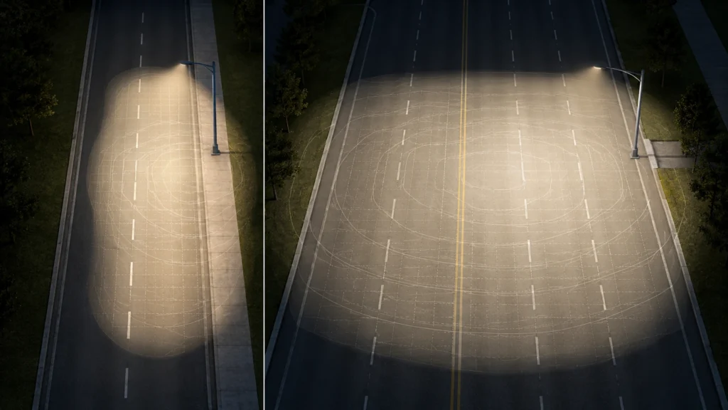
What Is Type II Optic Distribution?
Type II optic distribution is typically used when the lighting area is relatively narrow and the luminaire needs to distribute light along a more controlled lateral width.
It is often used for:
- narrow roads
- two-lane streets
- sidewalks
- walkways
- pedestrian paths
- village access roads
- residential access roads
- roads where the pole is installed near the edge of the carriageway
In practical roadway projects, Type II is commonly considered when:
- the road is narrow to medium in width
- the project has two lanes or two lanes plus sidewalk
- the pole is installed close to the road edge
- the required lateral coverage is not very wide
- glare control and spill light control are important
- the designer wants to avoid over-lighting areas outside the road
A useful rule of thumb is that Type II distribution is often associated with a lateral spread of about 1.0 to 1.75 times the mounting height, depending on the luminaire design and photometric file.
For example, if the mounting height is 8 meters, Type II may be suitable for a road or lighting zone that does not require very wide lateral throw.
But this is only an initial screening method. The real result still depends on the IES/LDT file, pole position, spacing, arm length, tilt angle, and project layout.
What Is Type III Optic Distribution?
Type III optic distribution is typically used when the lighting area is wider and the luminaire must project light farther across the roadway or site.
It is often used for:
- wider streets
- wider municipal roads
- intersections
- parking lots
- commercial roads
- wider residential roads
- layouts with larger pole setback
- roads where light must reach farther from the pole line
In practical roadway projects, Type III is commonly considered when:
- the road is wider than a basic two-lane layout
- the project includes wider traffic lanes, shoulders, or roadside activity zones
- the pole is installed at the side but needs to cover a wider carriageway
- the lighting area includes road lanes plus pedestrian or parking areas
- the project needs broader forward and lateral light distribution
- a parking lot or intersection needs wider coverage from fewer mounting points
Type III may support areas up to around 2.75 times the mounting height in lateral coverage, depending on the luminaire optics and actual photometric performance.
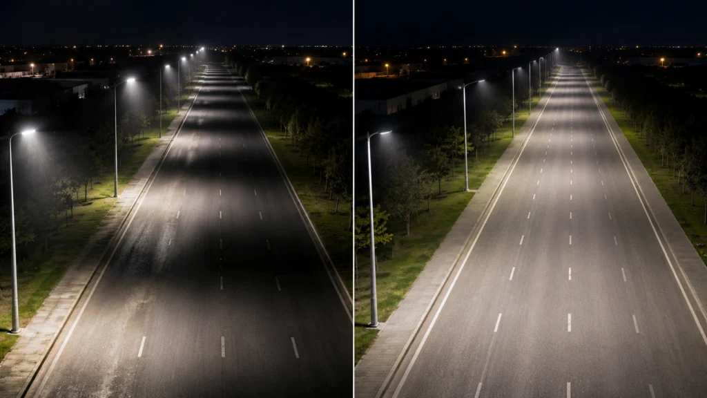
This does not mean Type III is always better. If Type III is used on a narrow road, it may send too much light outside the intended area, increase glare, reduce efficiency, or create unnecessary spill light.
Do Not Choose Optics by Lane Count Alone
Lane count is only a screening reference.
The actual optic depends on:
- road width
- pole position
- pole setback
- mounting height
- boom arm length
- luminaire tilt angle
- pole spacing
- lighting class
- sidewalk or shoulder condition
- photometric file performance
For example, a two-lane road with a large pole setback may still need a wider distribution. A wider road with median poles, opposite-side poles, or staggered poles may require a different layout.
This is why a simple rule such as “Type II for two lanes and Type III for three lanes” is not enough for engineering approval.
Type II vs Type III: Practical Comparison
| Review Point | Type II Optics | Type III Optics |
|---|---|---|
| Typical road type | Narrow-to-medium roads | Wider roads and broader areas |
| Common lane condition | Two lanes or two lanes plus sidewalk | Wider roads, intersections, parking areas |
| Lateral coverage | More controlled and narrower | Wider lateral projection |
| Typical use | Walkways, sidewalks, local streets, village roads | Wider streets, parking lots, commercial roads, intersections |
| Main advantage | Better control for narrow layouts | Better coverage for wider layouts |
| Main risk | May not reach enough width on wide roads | May cause spill light or glare on narrow roads |
| Solar project impact | May reduce wasted power if layout is narrow | May increase power demand if overused |
| Engineering check | Confirm road width, mounting height, spacing, and uniformity | Confirm glare, spill light, uniformity, and coverage limit |
| Final approval basis | IES/LDT + DIALux/Relux result | IES/LDT + DIALux/Relux result |
Do Not Confuse Lateral Distribution with Vertical Distribution
Type II and Type III describe lateral light distribution. They help explain how far the light spreads across the road width.
But roadway lighting design also depends on vertical or longitudinal distribution, which affects how light is projected along the road direction between poles.
Typical vertical distribution categories may include:
- Short distribution
- Medium distribution
- Long distribution
For example, a project may use Type II lateral distribution with a medium vertical throw, or Type III lateral distribution with a different longitudinal distribution.
This is why a simple “Type II or Type III” label is not enough for engineering approval.
For EPC and municipal projects, the optical review should include both:
- Lateral coverage — can the optic cover the road width?
- Longitudinal coverage — can the optic support the required pole spacing and uniformity?
How Road Lighting Standards Affect Optic Selection
Road lighting standards should be used as project review tools, not just as reference documents.
Standards such as the latest applicable version of ANSI/IES RP-8 and EN 13201 are commonly used to review road type, lighting class, visual task, uniformity, glare control, surrounding area conditions, maintenance assumptions, and acceptance requirements.
For a project team, this means the optic should not be selected first. The review should usually follow this logic:
- Define the road type and usage condition.
- Select or confirm the required lighting class.
- Confirm road width, lane arrangement, sidewalk, shoulder, and conflict areas.
- Confirm mounting height, pole spacing, arm length, setback, and tilt.
- Select a possible optical distribution.
- Run IES/LDT-based DIALux or Relux simulation.
- Check average level, uniformity, glare, spill light, and acceptance requirements.
- Adjust optic, wattage, pole spacing, mounting height, or layout if needed.
This approach is more reliable than choosing a luminaire only by wattage, lumen output, or a product catalogue picture.
How to Choose Between Type II and Type III Optics
The right choice depends on the project layout, not the product name.
Before choosing Type II or Type III optics, the project team should collect the road and installation inputs first.
1. Check the Road Width
Road width is usually the first screening factor.
If the road is narrow, such as a local road, access road, two-lane road, village road, or sidewalk-adjacent street, Type II may be a better starting point.
If the road is wider, such as a multi-lane municipal road, commercial road, intersection, or parking access road, Type III may be more suitable.
But road width alone is not enough. A narrow road with large pole setback may still need a wider distribution. A wider road with central median poles may require a different design logic.
2. Check the Mounting Height
Mounting height changes how far the light can spread across and along the road.
A higher mounting height can help distribute light over a larger area, but it may also affect:
- glare
- pole cost
- wind load
- foundation requirements
- maintenance method
- solar panel exposure in solar street lighting projects
A lower mounting height may fit pedestrian-scale streets better, but it can make uniformity and glare control harder if the spacing is too long.
For solar street lighting projects, mounting height also affects the pole structure, solar panel position, battery configuration, and wind exposure.
This is why optic selection should be reviewed together with the complete pole and system design.
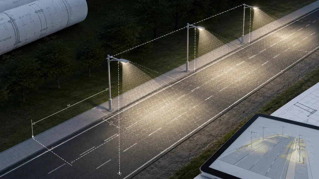
3. Check Pole Spacing
Pole spacing directly affects uniformity.
In many roadway projects, pole spacing may follow an approximate ratio of 3 to 4 times the mounting height, but the actual spacing must be validated by calculation.
If the spacing is too long, even the correct optic may create dark zones between poles. If the spacing is too short, the project may become over-designed and more expensive than necessary.
Type III optics may help wider coverage, but they cannot automatically fix unrealistic pole spacing.
The simulation must show whether the lighting level and uniformity can still meet the required standard or tender specification.
4. Check Pole Location and Arm Length
The same optic can perform differently depending on where the pole is installed.
Important layout inputs include:
- single-side pole arrangement
- opposite pole arrangement
- staggered pole arrangement
- central median pole arrangement
- pole setback from road edge
- boom arm length
- luminaire tilt angle
- sidewalk or shoulder position
- roadside parking or pedestrian activity area
For example, a Type II optic may work well when poles are close to a narrow road edge. But if the pole is set far back from the carriageway, the same optic may fail to deliver enough useful light across the road.
5. Check the Lighting Class and Acceptance Target
Optics should be selected based on the required lighting performance, not only visual preference.
Depending on the project standard and road type, the review may include:
- average illuminance
- average luminance
- overall uniformity
- longitudinal uniformity
- glare control
- threshold increment or disability glare indicator
- surrounding area ratio
- pedestrian visibility
- conflict area lighting
- field measurement method after installation
A luminaire can look bright in a sample photo but still fail the acceptance target if its distribution does not match the road geometry.
Simple Example: Why the Same Wattage May Need Different Optics
Assume a project uses an 8 m mounting height solar street light.
For a narrow two-lane access road with poles installed close to the road edge, Type II may provide better control and reduce wasted light outside the road.
For a wider municipal road with a larger pole setback, sidewalk, or roadside parking area, Type III may be a better starting point because the light must reach farther across the carriageway.
In both cases, the wattage may be similar.
The difference is not only power. The real difference is whether the optical distribution matches the road geometry and can pass the simulation result.
For solar street lighting projects, this also affects:
- battery sizing
- solar panel sizing
- autonomy design
- dimming schedule
- project cost
- long-term runtime reliability
This is why optical selection should be reviewed before finalizing wattage and system configuration.
Why IES/LDT Files Are Required Before Approval
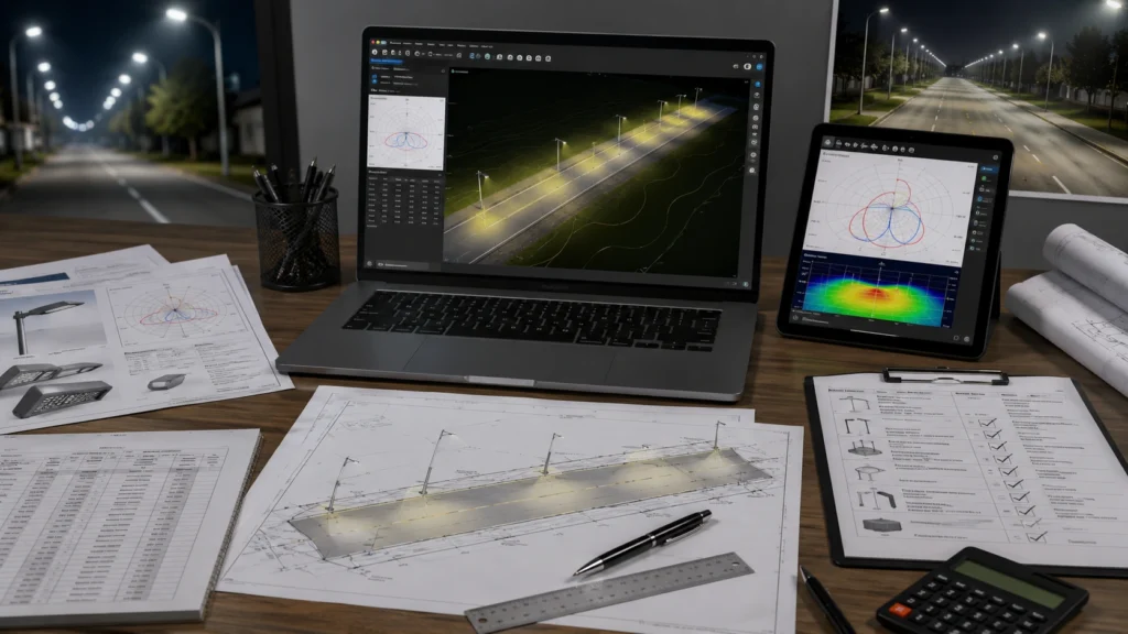
An IES or LDT file is the photometric data file used to calculate how a luminaire distributes light in a real layout.
Without this file, Type II or Type III is only a claim, not an engineering basis.
For tender and municipal review, the project team should ask for:
- IES or LDT photometric file
- luminaire datasheet
- pole height and spacing layout
- road width and lane arrangement
- mounting arm and tilt details
- DIALux or Relux report
- BOQ mapping
- installation drawing
- measurement and acceptance notes
This is especially important when different suppliers provide different optical labels. One supplier’s “Type II” and another supplier’s “Type II” may not produce the same result in the same project layout.
For project review, the simulation result is more important than the optic name.
For tender or EPC review, Sunlurio can help match the luminaire model, optical distribution, IES/LDT file, and DIALux or Relux report to the actual road layout.
Request Engineering Pack (24H)
What Buyers Should Check Before Accepting an Optic Proposal
Before approving a Type II or Type III proposal, buyers should check whether the supplier has provided enough information for engineering review.
A reliable roadway lighting proposal should include:
- road width and road type assumptions
- number of lanes and sidewalk or shoulder condition
- pole height and pole spacing assumptions
- pole arrangement and setback
- boom arm length and tilt angle
- luminaire model and optical distribution
- IES/LDT file
- DIALux or Relux calculation result
- average illuminance or luminance result
- uniformity result
- glare or spill light review when required
- datasheet and installation drawing
- BOQ mapping
- acceptance or measurement notes
If these items are missing, the buyer may still receive a quotation, but the project becomes harder to compare, approve, and execute.
Common Mistakes When Choosing Type II or Type III Optics
Mistake 1: Choosing by Wattage Instead of Distribution
Higher wattage does not guarantee better roadway lighting.
If the optic does not match the road width and pole layout, extra wattage may only increase glare, spill light, energy use, or battery demand in solar projects.
Mistake 2: Using Type III Everywhere
Type III may look safer because it offers wider coverage, but it is not always the right choice.
On narrow roads, it may send light beyond the intended area and reduce optical efficiency.
Mistake 3: Ignoring Pole Setback
Pole setback can change the result significantly.
A narrow road with a large setback may need wider distribution than expected, while a wider road with a better pole arrangement may not need excessive lateral throw.
Mistake 4: Ignoring Sidewalks and Pedestrians
Road lighting is not only for vehicles.
In municipal streets, pedestrians, cyclists, parking areas, bus stops, and roadside activities may also need visibility.
The optic should be reviewed against the complete right-of-way, not only the vehicle lane.
Mistake 5: Copying One Layout to Every Road
A layout that works for one road width, pole height, or lighting class may fail in another project.
Copying the same Type II or Type III solution across different road sections can create uneven lighting or failed acceptance results.
Mistake 6: Approving Without Simulation
A catalogue optic label is not enough for project approval.
EPC contractors and municipal teams should request DIALux or Relux outputs based on the actual road geometry and IES/LDT file.
Where Type II and Type III Optics Are Commonly Used
Type II optics are often suitable for:
- local roads
- narrow municipal streets
- two-lane roads
- sidewalks and walkways
- village access roads
- residential access roads
- roads with limited lateral width
- projects where spill light control is important
Type III optics are often suitable for:
- wider municipal roads
- wider residential roads
- commercial streets
- intersections
- parking lots
- roads with larger pole setback
- layouts requiring broader forward and lateral coverage
In real projects, these are only starting points. The final optic should be confirmed through lighting calculation.
How Sunlurio Supports Roadway Optic Review
Sunlurio supports roadway lighting projects by helping EPC contractors, distributors, municipal teams, and project owners review the optical distribution before final approval.
For roadway and solar street lighting projects, Sunlurio can support:
- Type II / Type III optic selection review
- IES/LDT photometric file support
- DIALux or Relux simulation output
- pole height and spacing review
- road width and lighting class input review
- datasheets and drawings
- BOQ and tender document support
- product configuration for solar, AC LED, or smart street lighting projects
This is useful when the project needs more than a product quotation.
For review-heavy tenders, the stronger approach is to connect:
- luminaire model
- optical distribution
- road layout
- IES/LDT file
- DIALux or Relux result
- BOQ item
- datasheet and drawing
- acceptance note
If your project needs a complete lighting review package, you can request an engineering support pack here:
Request Engineering Pack (24H)
Related Engineering Support
For project teams that need lighting calculation, photometric files, and tender-ready documents, these pages may help:
- Engineering Support
- IES Photometric Files
- DIALux Simulation Outputs
- Datasheets and Drawings
- Tender Documents and BOQ
- Road Lighting Simulation with DIALux EVO
- Solar Street Light Systems
- Contact Sunlurio
FAQ
What is the difference between Type II and Type III light distribution?
Type II distribution usually provides a narrower and more controlled lateral spread, while Type III distribution provides wider lateral coverage for broader roadways, intersections, parking lots, or layouts with larger pole setback. The final result should still be confirmed by photometric files and simulation.
Is Type II or Type III better for roadway lighting?
Neither is always better. Type II is usually better for narrower roads, sidewalks, and two-lane layouts. Type III is usually better for wider roads, intersections, parking lots, and broader lighting areas. The correct choice depends on road width, mounting height, pole spacing, pole position, lighting class, and the IES/LDT simulation result.
Which optic is better for a two-lane road?
Type II is often a better starting point for a two-lane road, especially when poles are close to the road edge. However, if the road has a large pole setback, wide shoulder, sidewalk, or roadside activity area, Type III may need to be tested in DIALux or Relux.
Can Type III replace Type II if I want more coverage?
Not always. Type III can provide wider coverage, but using it on a narrow road may increase spill light, glare, or wasted light outside the target area. Wider distribution does not automatically mean better design. It should be checked through DIALux or Relux calculation.
Is wattage more important than optic type?
No. Wattage only describes power consumption, not how the light is distributed. A lower-wattage luminaire with the correct optic may perform better than a higher-wattage luminaire with the wrong distribution. For project approval, photometric performance is more important than wattage alone.
Do I need IES or LDT files to choose Type II or Type III?
Yes. IES or LDT files are necessary for lighting calculation. Without photometric data, Type II or Type III is only a product description. The project team cannot properly verify road coverage, uniformity, glare, or compliance with tender requirements.
What information should I send before asking for optic selection?
You should provide road width, number of lanes, pole height, pole spacing, pole arrangement, pole setback, boom arm length, luminaire tilt, lighting class or target lux level, and whether sidewalks, intersections, parking areas, or pedestrian zones are included. These inputs allow the supplier to check the correct optic and run a meaningful simulation.
Are Type II and Type III optics used only for solar street lights?
No. Type II and Type III optics are used in both solar street lighting and AC LED street lighting. The optical logic is related to road geometry and lighting performance. For solar projects, however, the optic also affects power demand, battery sizing, autonomy, and system cost.
Should the optic be selected before or after DIALux simulation?
The optic can be selected as an initial assumption before simulation, but it should only be approved after simulation. In a professional workflow, the project team selects a candidate optic, runs the calculation, checks the results, and then adjusts the optic, wattage, mounting height, or pole spacing if needed.