Wind Resistance Engineering for Lighting Poles
Table of Contents
Part 1 — Strategic Overview
1. Executive Summary
Wind resistance is one of the most critical engineering factors affecting the safety, stability, and long-term performance of lighting poles used in roadways, urban streets, industrial zones, and solar street lighting systems. In severe wind regions, inadequate structural design may lead to pole bending, vibration fatigue, foundation failure, or complete structural collapse.
This white paper provides a concise and practical overview of wind resistance engineering for lighting poles. It explains how wind loads are formed, how they affect pole structures, and how proper design standards ensure long-term stability in real outdoor environments.
2. Why Wind Engineering Matters
Lighting poles are tall, slender structures that experience significant lateral wind forces. These forces increase exponentially with height and wind speed. A well-engineered pole must resist:
- static wind loads acting directly on the pole body
- dynamic wind effects such as vortex shedding and vibration
- additional drag from luminaires, arms, and solar panels
- fatigue stress from repeated wind cycles
Proper wind-resistant design ensures public safety, prevents structural failure, and reduces long-term maintenance costs for municipalities and EPC contractors.
3. Environmental Challenges in MEA Regions
Many countries in Africa and the Middle East experience extreme weather conditions, which directly impact lighting pole stability:
- high-speed desert winds (Saudi Arabia, Oman, UAE)
- coastal storms with strong gusts (Ghana, Angola, Kenya)
- open flat terrain with little obstruction (rural highways)
- thermal expansion from daytime heat and nighttime cooling
These conditions require lighting poles to meet higher structural reliability than poles installed in low-wind urban regions. This white paper outlines the engineering concepts required to meet these challenges.
Part 2 — Wind Load Fundamentals
4. Basic Wind Load Concepts
Lighting poles are slender vertical structures, which makes them highly sensitive to lateral wind pressure. Wind load increases exponentially as wind speed rises, and the total force acting on the pole is also influenced by its height, shape, and mounted equipment such as luminaires or solar panels.
In engineering terms, wind pressure is commonly estimated using a simplified relationship:
Wind Pressure ≈ 0.613 × V² (where V represents wind speed in m/s)
This demonstrates that even a moderate increase in wind speed results in a significant increase in load on the structure.
5. Key Factors Affecting Wind Load
Several environmental and structural factors determine how much wind force a lighting pole must withstand:
- Wind speed rating of the installation site
- Height of the pole (higher poles experience greater forces)
- Pole diameter and shape (tapered poles reduce drag)
- Fixture area including luminaires, arms, or solar panels
- Exposure category (open terrain, roadside, coastal zone)
Among these factors, height and wind speed contribute the most to overall wind force.
6. Static vs Dynamic Wind Effects
Wind forces can be divided into two main categories:
- Static wind loads — the direct force of wind pressing against the pole and fixtures.
- Dynamic wind effects — oscillations caused by vortex shedding, gusting, and turbulence.
Dynamic effects are especially important for tall or flexible poles. Without proper design, long-term vibration may cause structural fatigue, bolt loosening, or pole failure.
7. Wind Categories in MEA Regions
Africa and the Middle East include a wide range of wind zones:
- High-wind deserts: UAE, Oman, Saudi Arabia
- Coastal storm regions: Ghana, Angola, Kenya
- Flat rural highways with unobstructed wind exposure
- Urban zones with reduced wind impact
Pole designs must be adapted accordingly, ensuring both safety and long-term reliability under expected wind conditions.
Part 3 — Structural Engineering for Lighting Poles
8. Pole Geometry & Aerodynamic Shape
The geometry of a lighting pole directly affects its ability to withstand wind pressure. Most modern poles use a tapered octagonal or conical design, which reduces drag and distributes stress more evenly from top to bottom.
Aerodynamic pole profiles help lower wind-induced vibration and significantly improve long-term stability, especially in high-wind regions.
9. Wall Thickness, Tapering & Structural Strength
Wall thickness and tapering ratio determine how the pole responds to bending forces. Common engineering principles include:
- Thicker walls at the base for higher bending resistance
- Gradual tapering to reduce weight while maintaining strength
- Reinforcement at stress points (arm joints, bracket areas)
Proper tapering allows the pole to flex safely under heavy wind loads without collapsing.
10. Material Selection (Steel Grades & Corrosion Resistance)
High-quality steel is essential for structural reliability. Typical materials include:
- Q235 / Q355 steel for standard poles
- S355 / S500 for higher wind loads or tall structures
- hot-dip galvanizing for long-term corrosion resistance
In coastal regions, additional surface treatment (e.g., powder coating) is recommended to resist salt corrosion.
11. Impact of Brackets, Arms & Fixtures on Wind Load
Every attached component increases drag area, including:
- single or dual lighting arms
- solar panels
- smart pole antennas or sensors
- large luminaires
Engineering must account for the combined wind load of the pole body and all mounted accessories to ensure structural safety.
12. Foundation & Anchor System Engineering
The foundation is responsible for stabilizing the pole under wind pressure. Common foundation types include:
- anchor bolt cages set in reinforced concrete
- direct-buried foundations for rural/cost-sensitive projects
- heavy reinforced bases for high-wind coastal areas
Proper foundation depth and concrete strength are essential to prevent tilting, cracking or full structural failure during storms.
Part 4 — Wind Failure Mechanisms & Prevention
13. Bending, Buckling & Structural Failure
Wind pressure generates a bending moment on the lighting pole, with the highest stress typically occurring near the base. If the pole’s material strength, wall thickness, or taper design is insufficient, the pole may experience:
- permanent bending under extreme wind
- elastic deformation during storms
- catastrophic buckling when structural limits are exceeded
Proper design ensures that the pole can flex safely without reaching its failure threshold.
14. Vibration & Vortex Shedding
When wind flows around a pole, alternating air vortices may form, causing the pole to vibrate in a phenomenon known as vortex shedding. Over time, this leads to:
- metal fatigue
- weld cracking
- loosened bolts
- oscillation instability
Aerodynamic pole shapes, proper tapering, and thicker sections near the top can reduce vortex-related vibration.
15. Common Field Failures
Based on field studies in Africa and the Middle East, the following wind-related failures are most common:
- Pole base cracking from repeated stress cycles
- Arm failure due to oversized luminaires or panels
- Anchor bolt pull-out from inadequate foundation depth
- Corrosion weakening in coastal regions
- Pole-top oscillation on long or thin poles
16. Preventive Engineering Measures
The most effective ways to prevent wind-induced failures include:
- Using Q355/S355 steel or higher grades for tall poles
- Increasing wall thickness at the base and arm joint areas
- Applying hot-dip galvanizing plus powder coating for coastal use
- Designing deep reinforced foundations for high-wind coastal regions
- Using aerodynamic tapered shapes to reduce vibration
- Ensuring correct installation with proper torque and alignment
Together, these design principles significantly improve overall pole safety and minimize operational risk.
Part 5 — International Standards & Compliance
17. EN40 (European Standard for Lighting Poles)
The EN40 standard is the most widely referenced international specification for lighting poles. It defines structural requirements for:
- wind load classification
- material strength and steel grade selection
- foundation design and anchor bolt configuration
- fatigue resistance over the pole’s service life
EN40 forms the basis for many government tenders and EPC engineering designs, especially in Africa and the Middle East where wind load must be calculated with high accuracy.
18. AASHTO (American Association of State Highway and Transportation Officials)
The AASHTO LTS-6 standard defines wind load calculations for roadway structures, including lighting poles, sign support poles, and traffic masts. It covers:
- basic wind speed maps across different regions
- gust factor and turbulence intensity
- load combinations for structural reliability
- fatigue design based on vortex shedding
Many highway and motorway projects reference AASHTO as it emphasizes safety under frequent high-wind conditions.
19. IEC / ISO Standards
Several IEC and ISO standards relate to pole structures, coatings, and environmental protection:
- ISO 1461 — hot-dip galvanizing zinc coating standard
- ISO 9223 — corrosion categories for outdoor structures
- IEC 60068 — environmental testing (temperature, vibration, humidity)
- ISO 898 — mechanical properties of anchor bolts
Together, these standards ensure lighting poles maintain long-term structural safety and corrosion resistance under real-world conditions.
20. Compliance Requirements for MEA Government Projects
Most tender specifications in Africa and the Middle East require lighting poles to meet a combination of EN40, AASHTO, and ISO standards. Typical requirements include:
- wind resistance up to 100–160 km/h depending on region
- S355 steel or higher for structural durability
- hot-dip galvanizing for long-term corrosion protection
- engineered foundations with certified anchor bolts
- third-party structural calculations or stamped engineering drawings
Meeting these standards ensures long-term safety, reduces maintenance cost, and aligns with international best practices for public lighting infrastructure.
Part 6 — Engineering Recommendations for MEA Projects
21. Pole Sizing Recommendations by Wind Zone
Lighting poles installed in Africa and the Middle East must be sized based on the region’s expected wind speed and exposure category. General recommendations include:
- Urban areas (low exposure): 6–9 m poles with standard wall thickness
- Highways & open terrain: 8–12 m poles with reinforced base sections
- Coastal or desert zones: 10–12 m poles with S355 steel and thicker walls
- Storm-prone coastal regions: engineered poles rated for 140–160 km/h winds
Pole height, diameter, and steel grade should always match the project’s certified wind-load requirements.
22. Material & Coating Recommendations
To ensure long service life in extreme MEA conditions, recommended protective measures include:
- hot-dip galvanizing (ISO 1461 standard)
- powder coating for extra UV and corrosion protection
- S355/S500 steel for structurally demanding installations
For coastal applications, dual-layer coating is strongly recommended to prevent premature corrosion.
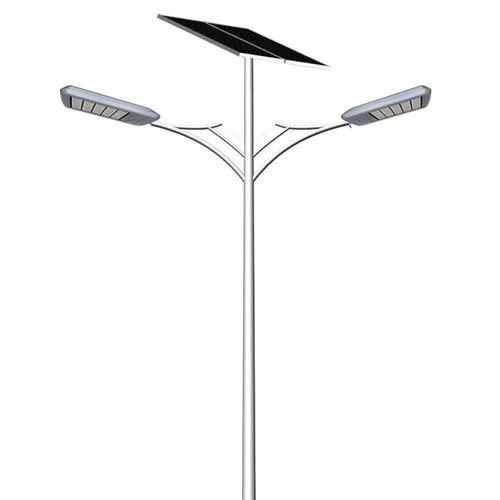
23. Design Considerations for Solar Street Lighting Poles
Solar street lighting poles experience higher wind stress due to the added surface area from:
- solar panels
- battery boxes
- large luminaires or brackets
Key engineering recommendations:
- use reinforced poles with increased wall thickness
- install aerodynamic panel brackets
- minimize exposed surface area to reduce drag
- design panel orientation for wind reduction, not only for sunlight
Proper engineering ensures safe operation during storms and extends service life in high-wind regions.
24. Deployment Guidelines for Desert, Coastal & Highway Zones
Lighting poles must be adapted to the region’s terrain and environmental conditions:
- Desert zones: high wind, sand abrasion, extreme heat—reinforced steel and thicker coatings required
- Coastal areas: high corrosion risk—hot-dip galvanizing + powder coating recommended
- Highways: open terrain exposure—poles must be rated for higher wind speed categories
- Mountain regions: gusting and turbulence—additional safety factor required in structural design
These guidelines help ensure long-term structural stability and minimize failure risk in diverse MEA environments.
Part 7 — Conclusion & Procurement Checklist
25. Summary of Engineering Best Practices
Wind resistance engineering is a critical factor in ensuring the long-term safety and stability of lighting poles, especially in regions with strong seasonal winds, open terrain exposure, and coastal environments. Proper design requires careful consideration of wind load calculations, material selection, pole geometry, and foundation engineering.
By applying international standards such as EN40, AASHTO, and relevant ISO guidelines, municipalities and EPC contractors can ensure that lighting poles meet the structural safety requirements necessary for public infrastructure in Africa and the Middle East.
Selecting high-quality steel, using proper surface protection, reinforcing pole bases, and designing adequate foundations ensure a durable system with reduced maintenance needs over its operational life.
26. Government & EPC Tender Checklist
The following checklist provides a straightforward guideline for evaluating lighting pole specifications in public tenders and engineering submissions:
Structural Requirements
- Wind load rating aligned with project wind zone (100–160 km/h typical ranges)
- Structural drawings certified to EN40 or AASHTO
- Verified steel grade (minimum Q355/S355)
- Calculated bending moment and stress analysis
- Vibration and fatigue resistance considerations
Pole Material & Coating
- Hot-dip galvanizing according to ISO 1461
- Optional powder coating for UV and salt protection
- Material certification from manufacturer
Foundation & Installation
- Anchor bolt grade certified to ISO 898
- Concrete strength and depth based on soil conditions
- Correct torque and installation alignment
For Solar Street Lighting Projects
- Wind load analysis includes panels, brackets, and luminaires
- Reinforced poles for panel surface area drag
- Engineered mounting structures to reduce wind uplift
- Orientation optimized for both sunlight and wind stability
Following this checklist ensures compliance with international safety standards and structural performance expectations—reducing risks, improving longevity, and ensuring reliable operation in high-wind environments.
Final Recommendation
For public lighting infrastructure in Africa and the Middle East, wind resistance must be treated as a primary engineering factor. By adopting strong materials, proven standards, and proper installation methods, lighting poles can achieve long-term stability even under extreme environmental conditions. This approach minimizes maintenance, enhances public safety, and ensures durability across the entire project lifecycle.
Author introduction