Skip to content

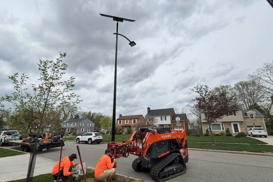
Solar street lights look simple from the outside – a pole, a lamp and a solar panel.
But from an engineering point of view, a solar street light is a tall, slender structure with:
- a large “sail” at the top (solar panel),
- sometimes a heavy battery on the pole or underground,
- often installed in exposed rural or coastal locations.
In many projects, the LEDs and panels are still fine after 5–8 years, but the foundations, anchor bolts and battery pits start to cause complaints and safety risks.
This guide explains how to design practical, safe solar street light foundations and battery pits for solar street lights, focusing on:
- wind loads and overturning risk
- foundation types and selection
- underground battery pit design (water, condensation, theft)
- real failure modes and how to avoid them
It is written for municipal engineers, EPC contractors, consultants and distributors who need reliable, documented solutions rather than trial-and-error.
💡 About Sunlurio
Sunlurio is a solar street light and steel pole manufacturer working with EPCs and municipalities in Africa, Asia and the Middle East.
We support projects with realistic wind load data, typical foundation drawings and battery pit concepts so your structural engineer and site teams can work faster and safer.
1. Why Solar Street Light Foundations Fail Before the LEDs
On paper, a solar street light is “maintenance-free”.
In reality, after a few rainy or windy seasons, many projects report:
- poles leaning or vibrating excessively,
- concrete around the base cracking or spalling,
- underground battery pits filling with water or rust,
- batteries being stolen or failing early,
- auditors asking:
“Where is the foundation and battery pit design?
Who checked the wind loads?”
From our field experience, most serious issues are not electronic. They are related to:
- underestimated wind loads on the solar panel (“sail effect”),
- copied grid-light foundations reused for solar lights,
- poor battery pit design (no drainage, no anti-condensation, weak covers),
- no coordination between civil, electrical and security requirements.
If you are responsible for a government tender, a PPP project or a long warranty, the real question is not “How many watts is the LED?”, but:
“Will this solar system stay structurally safe and maintainable for 10–20 years in our wind and soil conditions?”
This guide focuses exactly on that.
2. What Makes Solar Street Light Foundations Different from Normal Grid Poles
Many drawings on the market simply take a standard grid-powered LED pole foundation and apply it to a solar street light. That looks convenient, but it can be dangerous in high-wind or poor-soil areas.
2.1 The “Sail Effect” of Solar Panels
A solar panel is essentially a giant sail attached to the top of your pole.
Compared to a normal LED luminaire:
- the projected area of the panel is much larger,
- the panel is often tilted at 15–30°,
- the drag coefficient is different (a flat plate vs. a compact luminaire).
Under strong wind, the panel can attract much higher forces than the lamp itself. This significantly increases the bending moment at the pole base and the demand on the foundation and anchor bolts.
Pro Tip: Increasing the foundation size during construction might cost an extra US$50 per pole. Digging up and reinforcing a failing foundation two years later can easily cost US$500+ per pole (excavation, crane rental, new concrete, traffic management). In most projects, safety is actually cheaper when you decide correctly at the design stage.
2.2 Added Weight and Eccentric Centre of Gravity
Solar systems also change the weight distribution:
- pole + arm + luminaire + panel + bracket + cables,
- battery mounted on the pole or placed in an underground box.
The result is a higher and more eccentric centre of gravity compared to a simple grid light. Even if the pole height is the same, the foundation and anchor bolts often need to be stronger and better detailed for solar applications.
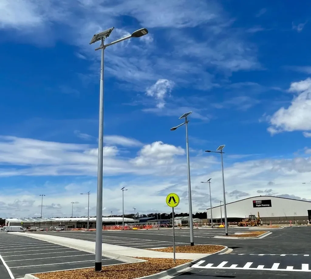
2.3 Typical Project Scenarios
Solar street lights are often installed where the grid is weak or unavailable:
- rural roads and villages with soft or variable soils,
- coastal areas and islands with strong winds and corrosion,
- hillsides and cut-and-fill slopes with unstable ground,
- industrial or security perimeters with high theft risk.
These environments make foundation and battery pit design even more critical.
3. Wind Loads: From Codes to Real-World Risk
We will not turn this into a full structural textbook, but we need the basic logic of how engineers think about wind loads for solar street lights.
3.1 Key Inputs for Wind Load Design
A typical wind load calculation for a solar street light foundation starts with:
- Basic wind speed
from national codes or wind maps (for example 30–50 m/s). - Terrain category
open field, suburban, urban, coastal, hillside, etc. - Structure height
total height of the pole and solar panel. - Effective projected area
of the pole, arm, luminaire, panel and brackets. - Importance / exposure factor
main roads, public squares, airports, ports or critical facilities may require higher safety factors.
Many engineers refer to standards such as:
- AASHTO (standards for support structures of lighting and signs),
- Eurocode 1 (Actions on structures – General actions – Wind actions),
- or equivalent national codes.
3.2 How Solar Panels Amplify Bending Moments
Even without going deep into formulas, one simple fact is clear:
- For the same pole height, adding a solar panel on top can increase the design bending moment at the base significantly compared to a bare LED pole.
In many practical configurations, the total design moment can be 30–80% higher once you include the panel area, tilt angle and combined wind effects.
You can think of it visually:
- V – horizontal wind force acting on the panel and luminaire
- h – height of the centre of pressure
- M = V × h – bending moment at the pole base
Higher wind speed, larger panel area and higher mounting point all push M upward. The foundation and anchor bolts must be sized accordingly.
3.3 When You Must Involve a Structural Engineer
For small poles in moderate wind zones, many projects rely on typical foundations from manufacturers.
However, you should definitely involve a qualified structural engineer when:
- basic wind speed is high (e.g. strong coastal winds, typhoon zones),
- pole height is ≥ 8–10 m,
- the solar panel area is large (multiple panels per pole),
- soil conditions are poor or variable (soft clay, fill, near water),
- the site is highly exposed (open terrain, hilltop, bridge).
In these cases, the safest approach is:
- use the manufacturer’s wind load and geometry data as input,
- let your local structural engineer design or check the foundations according to local codes.
As a manufacturer, Sunlurio provides realistic loading data and typical foundation concepts, so your engineer does not have to start from a blank page.
4. Foundation Options for Solar Street Lights
There is no single “best” foundation for solar street lights for all sites. The right option depends on:
- pole height and solar configuration,
- wind zone and terrain,
- soil bearing capacity and groundwater,
- battery placement strategy and theft risk,
- construction budget and local contractor capability.
Below are common foundation solutions and how they relate to solar street lights.
4.1 Spread Footing + Separate Underground Battery Pit
This is one of the most common arrangements for 6–10 m poles with underground batteries:
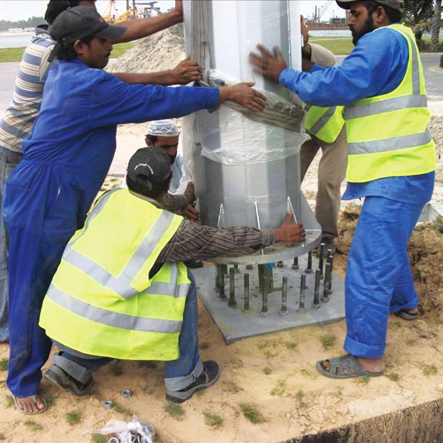
- a reinforced concrete spread footing foundation with anchor bolts,
- a separate underground battery box (pit) placed nearby,
- conduits connecting the pit, the pole and the distribution system.
Advantages:
- foundation and battery box can be constructed by the civil team using familiar methods,
- easy to inspect anchor bolts, base plate and grout,
- battery is relatively safe and protected underground.
Risks / attention points:
- the battery pit must be placed so it does not weaken the footing (no big voids cutting into the footing edge),
- cable routes must be planned on the drawing; electricians should not drill random holes in the concrete after casting,
- design battery pits with drainage and anti-condensation (see Section 5),
- vibration loosening: unlike static grid poles, solar poles can vibrate constantly under wind due to the panel “sail”. We strongly recommend using double nuts (locking nuts) on all anchor bolts to reduce the risk of loosening over time.
4.2 Integrated Foundation with Built-In Battery Compartment
Some projects use a precast or cast-in-place integrated foundation block that includes:
- an anchor bolt arrangement on top,
- an internal chamber for the battery and controller,
- access through a removable cover.
Advantages:
- fast installation if prefabricated,
- compact footprint,
- shorter cable runs.
Risks / attention points:
- the internal cavity must not compromise the structural capacity,
- water ingress and condensation risks increase with poor detailing,
- corrosion of steel parts can accelerate if water cannot escape.
4.3 Direct-Burial Poles with Underground Battery Boxes (Low-Height Systems)
For lower poles (e.g. 4–6 m) on rural roads, a direct-burial pole foundation with a simple underground battery pit may be acceptable in some projects.
Advantages:
- less concrete volume,
- simpler formwork and reinforcement,
- suitable for small community projects with limited budgets.
Risks / attention points:
- embedment depth and backfill compaction must be adequate for the wind zone,
- the underground battery box design still needs proper drainage, anti-condensation and anti-theft measures,
- soil variability across the site must be considered: a “typical” depth may not work everywhere.
4.4 Practical Selection Guide for EPCs and Municipalities
As a rough guide:
- 4–6 m poles, moderate wind, rural roads
→ direct-burial or small spread footing + underground battery box. - 6–9 m poles, mixed terrain, village roads / small towns
→ spread footing with anchor bolts + separate battery pit. - ≥ 9 m poles, high wind / coastal / important roads
→ engineered spread footing or pile / drilled shaft foundation + robust underground battery solution, always checked by a structural engineer.
For each project, Sunlurio can suggest a suitable foundation concept and typical dimensions based on pole height, solar configuration, wind zone and soil information.
5. Battery Pit Design: Waterproofing, Anti-Condensation & Anti-Theft
For solar street lights, the underground battery pit is often the most problematic point if not designed carefully.
A good battery pit should:
- keep the battery dry and ventilated,
- allow easy but controlled access for maintenance,
- be discreet and difficult to steal from,
- work with the foundation and cable routing rather than against them.
5.1 A “Breathing” Design: Drainage and Anti-Condensation
Many designs focus only on “waterproofing”, but a completely sealed box can still cause problems:
- temperature changes between day and night create condensation inside,
- water droplets form on cold surfaces and slowly damage terminals, cables and metal parts.
Practical recommendations for a “breathing” design:
- place a 20 cm layer of clean, coarse gravel (Ø20–40 mm) under the battery box to create a capillary break and allow rapid drainage,
- avoid placing the box directly on soft clay or impermeable soil,
- keep the cable entry point above the bottom of the box and seal around conduits,
- design the cover so that surface water flows away, not into the pit,
- include high-level ventilation holes with insect screens where appropriate.
A completely sealed underground box without drainage or ventilation can become a slow battery killer.
A well-designed pit allows water to escape and moisture to equalise without letting dirt and insects in.
5.2 Underground Battery Box Anti-Theft Strategies
In many regions, the battery is the most attractive component for thieves. A strong lock alone is often not enough.
Effective anti-theft strategies combine:
- Discretion – make the box less visible:
- cover level flush or slightly below ground,
- finish the top to blend with pavement or landscaping.
- Concealed locking points:
- internal lugs and locking bars,
- hidden hinges or robust internal pivot points.
- Structural resistance:
- sufficient thickness for the cover and frame,
- options for fixing the box to surrounding concrete or masonry.
In high-theft areas, making the battery harder to find and access is often more effective than just making the padlock bigger.
Sunlurio typically designs underground battery boxes with concealed hinges and internal locking points, so they are harder to identify and remove in the field.
5.3 Safety and Maintenance Access
A good design also respects the people who will work on the system:
- covers must not be so light that they deform,
- nor so heavy that two technicians cannot open them safely,
- hand grips or lifting points can make maintenance faster and safer,
- the box should allow technicians to inspect and replace batteries without needing to dig or break concrete.
By thinking about drainage, condensation, theft and maintenance together, you can avoid most battery-related complaints in solar street light projects.
6. Typical Failure Modes: What Can Go Wrong (and How to Prevent It)
Understanding how things fail in real projects helps you design them out from the start.
6.1 Structural and Overturning Failures
Symptoms:
- poles leaning or rotating over time,
- excessive vibration at the top of the pole in strong winds,
- solar panel brackets bent or torn.
Common causes:
- foundation sized for bare LED poles, not for solar panels,
- embedment depth or concrete volume underestimated,
- poor soil bearing capacity not considered,
- concrete not properly cured before installation and loading.
Prevention:
- always account for the panel area and sail effect in load calculations,
- respect minimum curing time for concrete before erecting poles,
- in high-wind or exposed sites, involve a structural engineer early.
6.2 Corrosion, Water Ingress and Battery Damage
Symptoms:
- standing water in battery pits,
- corroded terminals and cable lugs,
- batteries failing much earlier than expected.
Common causes:
- no drainage or gravel layer below the box,
- cable entry not sealed and acting as a water path,
- fully sealed box with severe condensation,
- aggressive soil or high groundwater ignored.
Prevention:
- design battery pits with drainage and anti-condensation,
- use proper seals around conduits and cable entries,
- specify suitable corrosion protection for metal parts in contact with soil.
6.3 Public Safety Risks and Liability
Symptoms:
- pole collapse near roads or public spaces,
- people tripping over damaged covers,
- exposed cables in damaged pits.
Common causes:
- foundations reused from unrelated projects without checking wind and soil,
- battery covers not rated for vehicle load where cars or trucks pass over,
- lack of inspection and maintenance routines.
Prevention:
- ensure foundation and pit designs are fit for purpose and properly documented,
- design covers to match actual traffic loads (pedestrian vs. light vehicle vs. heavy truck),
- implement a simple inspection checklist for the first years after installation.
7. Site Checklist for Solar Street Light Foundations & Battery Pits
Even the best drawings are useless if the site work is not controlled. A simple checklist can save many problems later.
You can adapt the following list into your own one-page PDF for supervisors and subcontractors.
Excavation & soil
- excavation dimensions match the drawings,
- unsuitable soft or loose material removed from the bottom,
- bearing soil firm and consistent.
Rebar, anchor bolts & templates
- reinforcement placed and tied as detailed,
- correct cover to concrete from all sides,
- anchor bolts fixed with a rigid steel template,
- bolt projection above finished concrete checked,
- bolt circle and orientation correct for the pole base plate,
- double nuts or locking nuts installed where specified.
Concrete & curing
- concrete grade matches specification,
- concrete properly compacted (no large voids or honeycombing),
- top surface finished to shed water away from the pole,
- adequate curing time allowed before installing poles and panels, especially in high-wind regions.
Battery pit & box
- pit dimensions, depth and position match the design,
- 20 cm gravel drainage layer installed where specified,
- box level and properly supported,
- cable entries at correct height and sealed after cabling.
Cables & conduits
- conduits placed before concrete is poured,
- no sharp bends that make cable pulling difficult,
- conduits and entries sealed to prevent water and insects,
- earthing / grounding connections installed as per design.
Final inspection
- pole verticality checked,
- covers closed and locked,
- all visible elements free from cracks, major defects or obvious water traps,
- installation photos recorded and stored with project documentation.
📥 You can easily turn this into a one-page PDF and use it as a standard Solar Street Light Foundation & Battery Pit Inspection Checklist "Solar Street Light Foundation & Battery Pit Inspection Checklist") for your site teams.
8. Mini FAQ for Municipal Engineers and EPC Contractors
Q1. Do I need a different foundation for solar and grid-powered street lights of the same height?
Yes, in most cases you do. The solar panel adds significant projected area and changes the wind load and centre of gravity. Using a foundation designed for a bare LED pole can be unsafe in windy or exposed locations.
Q2. How deep should I bury the underground battery box?
There is no single depth for all projects. It depends on soil, frost depth, traffic loads and theft risk. In many rural applications, the box is buried deep enough to be out of sight, with a cover designed for pedestrian or vehicle loads, and with a drainage layer below.
Q3. Can I use the same foundation drawing for all sites in one project?
Only if the wind zone, terrain and soil conditions are similar. For long road projects crossing different terrains, it is common to have several foundation types or at least to check the “worst-case” sections carefully with a structural engineer.
Q4. When is a structural engineer absolutely necessary?
Whenever you have high wind speeds, tall poles, large panel arrays, poor soils or critical public areas (main roads, schools, hospitals, airports), a structural engineer should check or design the foundations. Manufacturer data is a starting point, not a replacement for local engineering.
Q5. How can I justify a slightly bigger foundation cost to my client?
By focusing on risk and lifetime cost. A modest increase in concrete volume and proper battery pit design can avoid:
- early battery failures and replacements,
- structural repairs and safety incidents,
- disputes with insurers, auditors and the public.
This is usually a very good trade-off for serious projects.
9. How Sunlurio Supports Your Off-Grid Street Lighting Projects
Sunlurio is not only a supplier of solar street lights and poles. We act as a technical partner for government and EPC projects.
For off-grid solar street lighting, we can:
- supply integrated systems: poles, brackets, panels, luminaires and battery solutions that work together,
- provide typical foundation and battery pit concepts aligned with your pole heights and wind zones,
- share realistic wind load and weight data for your structural engineers,
- review your existing foundation drawings and battery pit details from a practical field perspective.
✅ Planning a new off-grid solar street lighting project?
Already have a foundation drawing from another supplier, or need a second opinion?
Send us your pole heights, solar configuration, wind zone and basic soil information. Our engineers can prepare a solar street light + foundation + battery pit suggestion to support your design, tender or approval process.
👉 Send My Pole Schedule
👉 Request a Free Foundation Review