A hot-dip galvanized street light pole is a steel lighting pole protected by a zinc coating to reduce corrosion in outdoor environments. In practical projects, however, the real decision is rarely just “galvanized or not.”
For EPC contractors, municipalities, and infrastructure buyers, the more useful questions are:
- Does the galvanizing comply with EN ISO 1461?
- Is coating thickness verified by inspection lot and sampling plan?
- Are the base plate, welds, anchor bolts, and wall thickness coordinated correctly?
- Can the pole height, spacing, and optics actually support the required roadway lighting performance?
That is why galvanized street light poles should be evaluated as part of a tender, structure, and lifecycle decision, not only as a product finish choice.
Quick Answer
A galvanized street light pole matters because it helps reduce corrosion risk and extend service life in outdoor infrastructure. But in real procurement, “galvanized” alone is not enough.
A better project review should confirm at least five things:
- EN ISO 1461 compliance
- coating thickness requirements by steel thickness
- inspection lot sampling and thickness records
- base plate and anchor bolt coordination
- IES photometric files and DIALux/AGi32 layout validation for spacing and uniformity
In practical terms, the safest procurement logic is:
- specify EN ISO 1461
- confirm the steel thickness interval
- require local and mean coating thickness records
- lock the foundation interface early
- verify the lighting layout, not just the pole supply
Need help matching pole specs, galvanizing requirements, and lighting layout for an EPC or municipal project?
Explore Solutions
Request Engineering Support (24H)
Why Galvanized Street Light Poles Matter in Infrastructure Projects
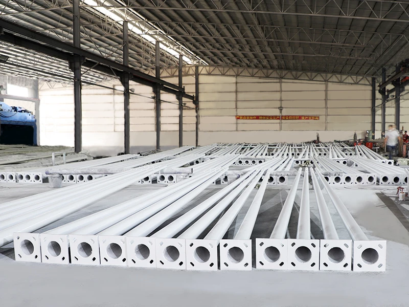
ALT: hot dip galvanized street light poles stacked in factory yard with octagonal tapered shafts
Caption: In infrastructure procurement, galvanizing is mainly about corrosion control, lifecycle cost, and reduced maintenance risk.
A galvanized street light pole is usually fabricated from structural steel and then dipped into molten zinc to form a protective coating. This coating slows corrosion and helps protect the pole in outdoor service.
That matters especially in:
- coastal roads
- ports and waterfront areas
- high-humidity and rainy regions
- rural highways with limited maintenance access
- urban arterial roads where lifecycle cost matters
For project buyers, galvanizing is mainly about risk reduction and maintenance control, not appearance alone.
Why “Galvanized” Is Not Enough
Two poles can both be described as “hot-dip galvanized” and still perform very differently in service.
That is why procurement teams should not stop at brochure language. The more useful review is:
- Which standard applies?
- What minimum thickness is required?
- How is thickness measured?
- How many poles or parts are sampled in each lot?
- What happens if transport or handling damages the coating?
Without those checks, the project may face:
- early rusting around welds and service doors
- base plate corrosion
- acceptance disputes
- repainting or replacement sooner than expected
EN ISO 1461: What Buyers Should Check
If the tender or BOQ only says “hot-dip galvanized”, it is incomplete.
A more reliable specification should include:
- the standard — EN ISO 1461
- minimum coating thickness requirements
- inspection lot sampling rules
- repair requirements for damaged areas after handling or transport
Minimum Coating Thickness for Non-Centrifuged Articles
Minimum values depend on the steel section thickness.
| Steel thickness interval (t) | Minimum local thickness (μm) | Minimum mean thickness (μm) |
|---|---|---|
| t > 6 mm | 70 | 85 |
| 3 < t ≤ 6 mm | 55 | 70 |
| 1.5 < t ≤ 3 mm | 45 | 55 |
| t ≤ 1.5 mm | 35 | 45 |
Minimum Coating Thickness for Centrifuged Articles
| Product type | Steel thickness interval (t) | Minimum local thickness (μm) | Minimum mean thickness (μm) |
|---|---|---|---|
| Threaded products | t > 6 mm | 40 | 50 |
| Threaded products | t ≤ 6 mm | 20 | 25 |
| Others | t ≥ 3 mm | 45 | 55 |
| Others | t < 3 mm | 35 | 45 |
These values are useful because they make the tender more auditable. The project is no longer relying on vague “anti-rust” wording. :contentReference[oaicite:1]{index=1}
Inspection Lot Sampling: Why It Should Be Written Into the Tender
EN ISO 1461 also defines the minimum number of articles to check in each inspection lot.
| Number of articles in the lot | Minimum number of articles in the control sample |
|---|---|
| 1–3 | All |
| 4–500 | 3 |
| 501–1200 | 5 |
| 1201–3200 | 8 |
| 3201–10,000 | 13 |
| Over 10,000 | 20 |
This matters because a supplier can only claim compliance credibly if the project knows:
- what the inspection lot is
- how many samples are measured
- how local and mean thickness are recorded
- whether the measuring method is calibrated and traceable
Practical Tender Clause (Copy and Paste)
Tender Clause – Hot-Dip Galvanizing:
Hot-dip galvanizing shall comply with EN ISO 1461. Coating thickness shall meet the minimum local and mean thickness requirements for the relevant steel section thickness intervals. Thickness shall be verified using a calibrated magnetic gauge, and sampling size shall follow EN ISO 1461 control sample rules based on inspection lot size. Any damaged areas after handling or transportation shall be repaired using suitable zinc-rich materials compatible with galvanized coatings.
This kind of clause makes the procurement requirement clearer and reduces dispute risk later. :contentReference[oaicite:2]{index=2}
How to Inspect Galvanizing on Street Light Poles
ALT: zinc coating thickness measurement using a magnetic gauge during galvanizing inspection
Caption: Thickness records by inspection lot are more useful than generic claims that a pole is “fully galvanized.”
A good supplier should be able to support a simple and auditable inspection trail.
What to Check
- measurement method — calibrated magnetic thickness gauge
- measurement location — avoid edges, holes, and non-representative points
- records — local and mean thickness logs by inspection lot
- packing method — especially around base plates, door edges, and contact points
What to Request as Proof
- thickness report by inspection lot
- sampling plan
- inspection-lot definition
- optional photos of thickness measurement
- packing protection details to reduce transport damage
Key Pole Engineering Specs to Put in a BOQ
Galvanizing is important, but it is not the only thing that determines performance.
A BOQ for street light poles should also lock the structural interface clearly.
Pole Geometry and Structure
- pole height
- mounting height
- shaft type: tapered octagonal / round / polygonal
- wall thickness range
- service door size and location
- arm or bracket type
- luminaire mounting detail if needed
Base Plate and Anchor Bolts
- base plate dimensions and thickness
- bolt circle diameter
- hole diameter
- anchor bolt size, grade, quantity, and length
- anchor bolt template drawing
Welding and Fabrication
- weld type and inspection requirement
- straightness or fabrication tolerance if project-defined
- galvanizing after full fabrication, not before
Quick BOQ Table
| Item | Specify in BOQ |
|---|---|
| Galvanizing standard | EN ISO 1461 |
| Pole height | ___ m |
| Shaft type | Tapered octagonal / round / polygonal |
| Wall thickness | ___ mm (range) |
| Base plate | mm thick, x ___ mm |
| Bolt circle | mm, holes mm |
| Anchor bolts | M x pcs, grade , length |
| Arm/bracket | outreach ___ mm, single/double |
| Submittals | drawings, thickness records plan, packing list, warranty |
Base Plate and Anchor Bolt Coordination Matters
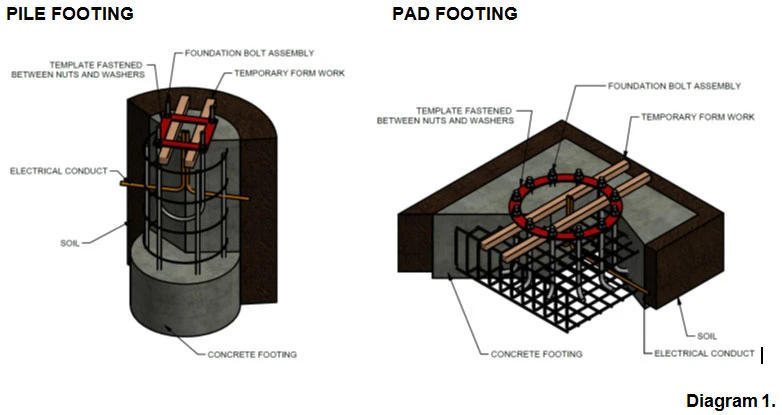
ALT: base plate and bolt circle detail with anchor bolt template for foundation coordination
Caption: Base plate and anchor bolt mismatch is one of the fastest ways to create foundation rework on site.
Many site delays happen not because the pole itself is wrong, but because the base plate, bolt circle, and anchor bolt template were not locked early enough.
That can lead to:
- foundation rework
- installation delay
- alignment issues
- site acceptance disputes
For related structural coordination, see:
Light Pole Foundation Design Basics
Roadway Lighting Performance: Height, Spacing, and Uniformity
Poles do not create lighting performance by themselves. Acceptance usually depends on the combination of:
- mounting height
- spacing
- bracket outreach
- luminaire optics
- roadway geometry
A practical roadway workflow is usually:
- define average illuminance and uniformity targets
- select the luminaire and exact IES file
- simulate the layout in DIALux or AGi32
- confirm mounting height, outreach, tilt, and spacing
- lock BOQ quantities and drawings
Practical Spacing Estimate
To check whether the procurement logic aligns with the required lighting performance, an engineering estimate can be used:
Spacing = (LL × CU × LLD × LDD) / (E_h × W)